- Joined
- Jun 17, 2011
- Messages
- 2,062
I picked up a set of 5C collets a while back, along with a spin indexer, and there have been a few times I've seen the advantage of having a fairly precise work-holding method for the lathe that allows the stock to extend into the spindle.
I got the chuck finished today, so it's time to post the build. I followed Pat Ioop's design, with a few small revisions.
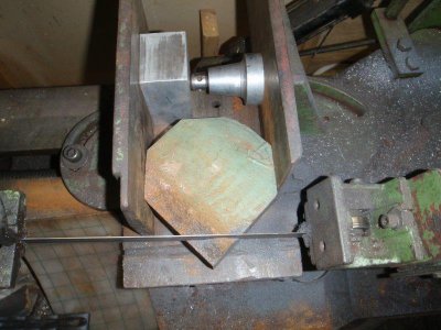
The back plate started out as a broken lump of cast iron, just barely large enough for the required piece. The big bandsaw did a good job of trimming it to an octagonal shape.
A 10 1/2" four-jaw is just the ticket for roughing out a big piece of cast...
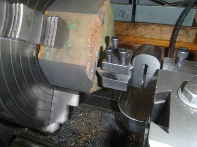
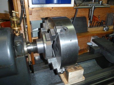
But, when it comes time to check the fit of the thread on the spindle, without removing it from the chuck, you have to wrestle the whole assembly around to screw it onto the spindle. Amazingly, even with the weight of the four-jaw hanging way out from the spindle, the register surface inside the chuck had a TIR of only around 4 thou.
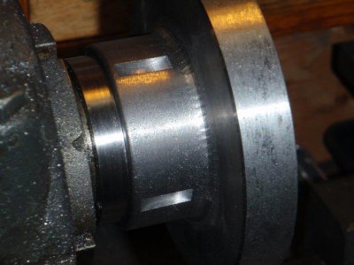
In order to make it easier to loosen the 5C chuck from the spindle, I cut four slots in the neck to allow use of a spanner.
Next, I needed a big chunk of steel to make the nose piece for the chuck. It takes along time to cut through a 7" x 4" cross section. The first cut gave me a 40 pound block.
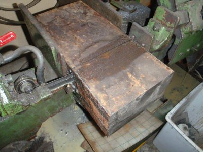
By the time the block was reduced to a 5 1/8" octagon, 4" long, it was reduced to 25 pounds. The long rod in the tailstock is my wiggler - 10" of music wire with a collar clamped on to make a better place to reference the DTI.
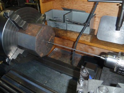
The nose piece is roughed out to a bit larger than required and a 1" hole drilled through it.
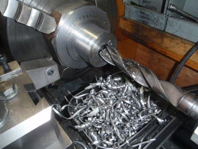
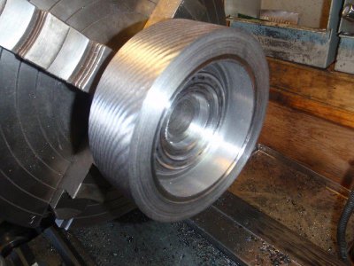
The nose piece was turned around and indicated carefully to keep it concentric. Then the inside features were shaped out with a boring bar. Note the stylish spiral knurling on the outside of the piece... Oh, alright! it's chatter! Ya happy now? I found out I had issues with the spindle bearings.
- - - Updated - - -
At this point, I went to the Hercus lathe to make the collet nut. I had some 3 1/2" round stock, so I made the nut a bit smaller than the plans called for.
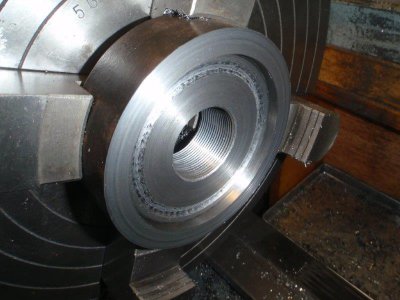
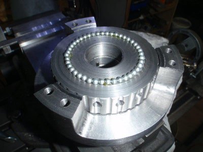
The plans show both sides of the nut grooved to take ball bearings. I used BBs, since I had a tube of them. I spent some time sorting them by size. I ended up using 0.173" balls for the front of the nut and 0.172" ones for the back side.
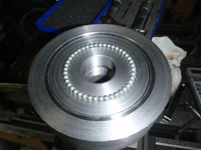
Once the nut was finished, I needed to find out how deep to cut the groove in the back plate to allow a bit of slack between the two sets of ball bearings. One set is only loaded when the nut is tightened and the other set when the collet is being loosened. I loaded both sets of bearings between the nose piece and the back plate and measured the gap with feeler gauges. This information let me cut the groove deep enough to allow a loose fit.
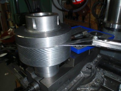
On to finish the outside of the nut. This is the first time I've used the tailstock with my dividing head. It adds a bit more rigidity to the setup.
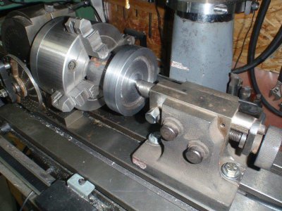
The grooves were cut with a 3/16" ball end mill. Then the holes were drilled and reamed for the tommy bar.
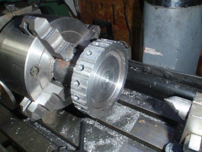
Time to drill the holes for the bolts that will join the nose piece to the back plate. You can see why we recommend getting the biggest mill you have space and budget for. I needed stubby drill bits to do this job.
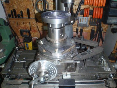
Once the two halves were clamped together, the only machine I had that could handle the height was the bigger drill press. The dividing head just made a good vise to hold it all.
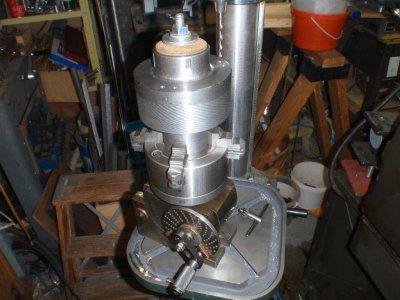
Once the drilling, tapping and counterboring were done, the two pieces could be bolted together and mounted directly on the spindle and the outside matched up a bit.
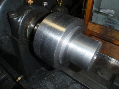
A major concern was how to cut away the steel on the nose piece to leave the three gaps for access to the collet nut. I started out with the obvious method of milling down from above, but the endmill caught in the metal and started to unscrew the chuck from the dividing head. Swinging the DH down to horizontal made it easier to control. I cut in on either side of the three bolt posts with a 9/16" endmill. Then, rather than mill away at all that steel, I drilled down a row of 1/4" holes that allowed the three pieces to be broken out.
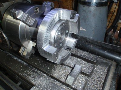
Once the cutouts were finished, it was time to bore the hole for the collets to finished size. Notice the 'stepped' arrangement of the steel, left to allow enough material for rounded fillets.
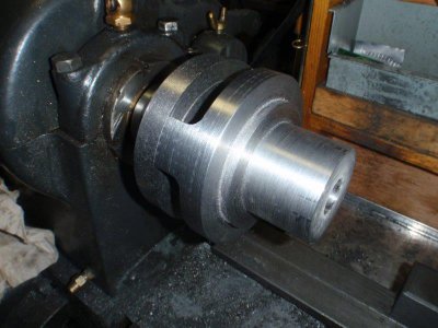
I took a lot of time boring the collet tunnel and taper. The whole project hinges on this being accurate. I'm pleased with the result.
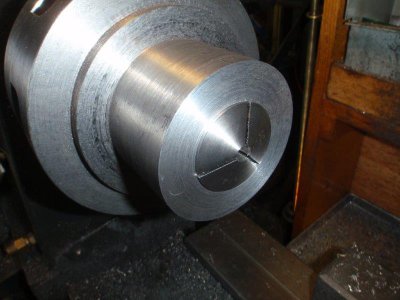
The key that engages with the slot in the side of the collet is held in a collar inside the body of the chuck. The hole through the collar is turned when the hole through the nose piece is bored and the key made and inserted later.
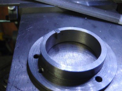
Final assembly, with a bit of grease in the bearing grooves.
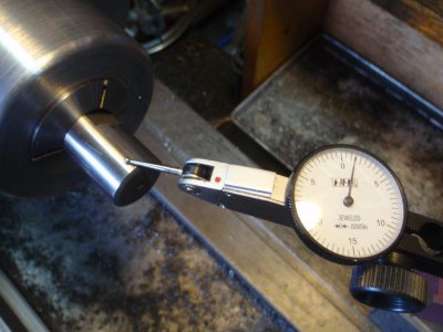
The proof of the job is in the measurement of the runout. It came out at 8 to 10 thou But then, every chuck needs to be coaxed into its optimum position. I loosened the bolts and gave it some careful taps. That brought it down to 0.0015-ish. I can probably tweak it a bit closer, if I take some time with it.
Thanks for taking the time to read through this somewhat long process. The designer mentioned that this type of collet nut is a lot faster to use that a keyed design would be. Changing collets by turning a key would take a long time. With the ball bearings, the nut in this style spins onto the threads very quickly. Then the tommy bar pulls it all up tight.


I got the chuck finished today, so it's time to post the build. I followed Pat Ioop's design, with a few small revisions.
The back plate started out as a broken lump of cast iron, just barely large enough for the required piece. The big bandsaw did a good job of trimming it to an octagonal shape.

A 10 1/2" four-jaw is just the ticket for roughing out a big piece of cast...

But, when it comes time to check the fit of the thread on the spindle, without removing it from the chuck, you have to wrestle the whole assembly around to screw it onto the spindle. Amazingly, even with the weight of the four-jaw hanging way out from the spindle, the register surface inside the chuck had a TIR of only around 4 thou.

In order to make it easier to loosen the 5C chuck from the spindle, I cut four slots in the neck to allow use of a spanner.

Next, I needed a big chunk of steel to make the nose piece for the chuck. It takes along time to cut through a 7" x 4" cross section. The first cut gave me a 40 pound block.

By the time the block was reduced to a 5 1/8" octagon, 4" long, it was reduced to 25 pounds. The long rod in the tailstock is my wiggler - 10" of music wire with a collar clamped on to make a better place to reference the DTI.

The nose piece is roughed out to a bit larger than required and a 1" hole drilled through it.

The nose piece was turned around and indicated carefully to keep it concentric. Then the inside features were shaped out with a boring bar. Note the stylish spiral knurling on the outside of the piece... Oh, alright! it's chatter! Ya happy now? I found out I had issues with the spindle bearings.

- - - Updated - - -
At this point, I went to the Hercus lathe to make the collet nut. I had some 3 1/2" round stock, so I made the nut a bit smaller than the plans called for.

The plans show both sides of the nut grooved to take ball bearings. I used BBs, since I had a tube of them. I spent some time sorting them by size. I ended up using 0.173" balls for the front of the nut and 0.172" ones for the back side.

Once the nut was finished, I needed to find out how deep to cut the groove in the back plate to allow a bit of slack between the two sets of ball bearings. One set is only loaded when the nut is tightened and the other set when the collet is being loosened. I loaded both sets of bearings between the nose piece and the back plate and measured the gap with feeler gauges. This information let me cut the groove deep enough to allow a loose fit.

On to finish the outside of the nut. This is the first time I've used the tailstock with my dividing head. It adds a bit more rigidity to the setup.

The grooves were cut with a 3/16" ball end mill. Then the holes were drilled and reamed for the tommy bar.

Time to drill the holes for the bolts that will join the nose piece to the back plate. You can see why we recommend getting the biggest mill you have space and budget for. I needed stubby drill bits to do this job.

Once the two halves were clamped together, the only machine I had that could handle the height was the bigger drill press. The dividing head just made a good vise to hold it all.

Once the drilling, tapping and counterboring were done, the two pieces could be bolted together and mounted directly on the spindle and the outside matched up a bit.

A major concern was how to cut away the steel on the nose piece to leave the three gaps for access to the collet nut. I started out with the obvious method of milling down from above, but the endmill caught in the metal and started to unscrew the chuck from the dividing head. Swinging the DH down to horizontal made it easier to control. I cut in on either side of the three bolt posts with a 9/16" endmill. Then, rather than mill away at all that steel, I drilled down a row of 1/4" holes that allowed the three pieces to be broken out.

Once the cutouts were finished, it was time to bore the hole for the collets to finished size. Notice the 'stepped' arrangement of the steel, left to allow enough material for rounded fillets.

I took a lot of time boring the collet tunnel and taper. The whole project hinges on this being accurate. I'm pleased with the result.

The key that engages with the slot in the side of the collet is held in a collar inside the body of the chuck. The hole through the collar is turned when the hole through the nose piece is bored and the key made and inserted later.

Final assembly, with a bit of grease in the bearing grooves.

The proof of the job is in the measurement of the runout. It came out at 8 to 10 thou But then, every chuck needs to be coaxed into its optimum position. I loosened the bolts and gave it some careful taps. That brought it down to 0.0015-ish. I can probably tweak it a bit closer, if I take some time with it.

Thanks for taking the time to read through this somewhat long process. The designer mentioned that this type of collet nut is a lot faster to use that a keyed design would be. Changing collets by turning a key would take a long time. With the ball bearings, the nut in this style spins onto the threads very quickly. Then the tommy bar pulls it all up tight.


Last edited by a moderator:

