- Joined
- Mar 22, 2017
- Messages
- 57
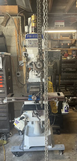
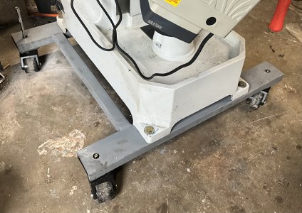
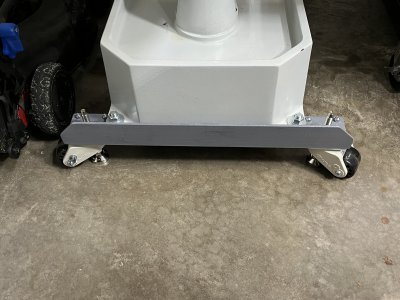
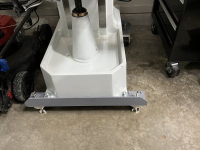
David moves his machine with a narrow pallet jack. I intend to move my machine with the caster-level. As one moves the machine, a wheel may encounter an obstruction of some sort that will introduce a lateral force on the angle iron and, more significantly, a torsional moment tending to twist it out of position. I am using 3"x4" 3/8" thickness that has to become an integral part of the base. The only reaction forces and moments to such a perturbation, are provided by the all-thread that ties the angle iron to the base and the friction/vertical wall between the angle iron and the base.Of course it is. But I have the right to compliment him on a very well executed design.
Perhaps they are, perhaps not. But my point about isolating forces remains valid. In Engineering, you are taught to recognize all forces, what is in tension and what is in torsion. No need for FEA to do this.
- You may build things any way you choose. I'm pretty sure I'd like your design also.
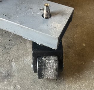
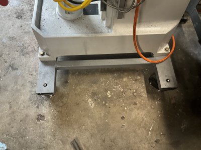
The 5/8" all-thread is stout and has a "clamped" end conditions both at the top of the base and at the connection to the angle iron. The applied torsional moment will tend to bend that all-thread. The friction between the angle iron and the bottom of the base will counter-act the force introduced by this "bump" as well as the vertical wall resting against the angle iron (this reaction is dependant on the direction of the perturbation). My concern is mainly the torsion- it will tend to bend the 10"-all-thread, or at the very least, introduce stresses on the 5/8"-11 nuts' connection that will tend to losen them.
As Dabbler said, there are potential torsional torques that one will see only because I am designing for moving the machine. For David, he does not have that problem, as he picks up the machine and moves it with a pallet jack.
I have prepared a 1/4-model in solidworks to run some FEA simulation (as Dabbler said, a simple engineering static analysis will suffice, but why not go all out and run a simulation). I suspect that for low enough obstruction force (bump on the wheels), the tie rods may not be needed. But they do provide a mitigation to counter-act that torsional moment should it arise. That was the reason why I added the tie rods. Notice that the entire assembly becomes a torsional box that is a lot more stable with these tie rods. Below may help illustrate the perturbation and the reaction moment I am stipulating.
Once I run the simulation with few loading conditions, I will post the results.