- Joined
- Jul 26, 2011
- Messages
- 4,142
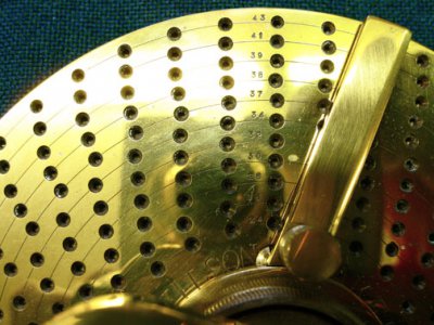
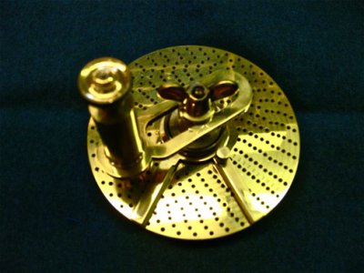
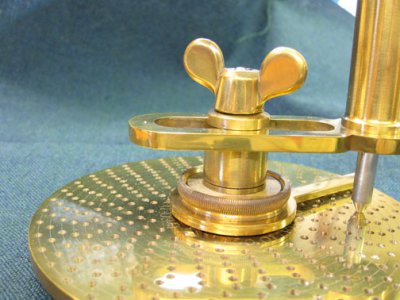
I thought it time to post some actual machining work rather than hand work!! This brass indexing attachment was made for my 6" rotary table.
Believe it or not,I spaced all the holes with a simple Starrett divider with square legs(Fay legs). After marking out the holes,I hand center punched the marks,and drilled each punch mark with a pump drill I also made,including the spade bits for it.
I found that often I could come out nearly right on the mark,with one extra adjustment to get the desired spacings after I had gotten going.
The pump drill is a simple drill which you push down on the handle and start the wheel rotating. Then,it's up and down on the wooden cross bar. The good thing is,you are drilling slowly,and if the drill gets a bit off center,you can tilt the drill and get it back on center perfectly. This must be done before the spade bit gets its corners fully into the hole.
After I got the holes done,I used a small center bit in the drill press to deepen and bevel the edges of the holes.
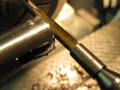
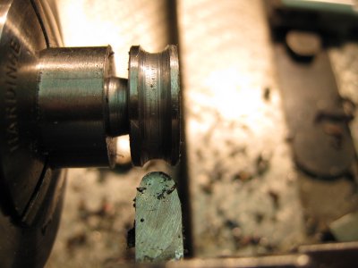
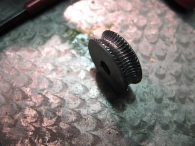
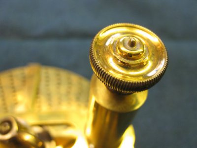
The knurls seen are the old fashioned microscope type knurls no longer available. I made these knurls too. They were made by running blank knurls horizontally against a rotating tap held in collet chucks in the lathe. The tap does a nice job of hobbing the teeth of the knurl,if all is done correctly,and the knurl rotates freely.
This dividing attachment has developed a beautiful dark golden patina which I only use clean gloves to handle. So far,it is still undisturbed in the finish after decades.
I have included a few pictures of making a knurl. I had made several other pictures,but they are bad,so I need to re do the knurl making process and re present it at another time. My little digital camera has an auto focus that is unreliable. Other than that,I am not a good photographer anyway!
I will advise anyone attempting to make these knurls to use a 3 or 4 flute tap,so at least 1 row of teeth is engaged all the time,to keep the knurl rotating. You also can tilt the knurl about 20 degrees to make a rope type knurl. Too much tilt,and the teeth of the tap start cutting on their back sides,making a mess.
The knurl needs also to be cut hollow pretty close to the diameter of the tap,or it will not work,and you will end up with a mess. That is,the hemispherical groove you cut in the wheel blank needs to match the diameter of the tap reasonably well. If not,the knurl will not turn out properly,and may be ruined.


Last edited:


 Mike
Mike