A Complete 13.8 Volt, 50 Amp Power Supply

I am trying to find transformer secondary minimum voltage. Is there any voltage drop across the pass transistors?

As I explained in the beginning of the page:
I would not recommend a secondary voltage of more than 18 volts. This is because the higher the secondary voltage is the more the pass transistors will have to drop to provide the 13.8 volts needed at the output. When high current is drawn a lot more heat will have to be dissipated by each transistor if the secondary voltage is high.

Petros
 
I am trying to find Minimum secondary voltage not maximum..
 
I would give a couple more volts from the needed to play safe..
 
let's say we have V secondary voltage.
It is 1.414V peak voltages.
after full wave rectifition voltage drop it will ne 1.414V-1.4 volts.
lm723 voltage drop about 2v
then after IC voltage will be 1.414V-1.4-2 volts. this will be output voltage if there is no other voltage drop in this circuit.
 
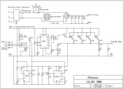
Hi, may be a stupid request, sorry, but how can I obtain the full circuit diagram (figure 1) in a better resolution ?
Can only see a picture 600x434, cannot see all details...
Thanks
 
Hi Petros
First of all, a great thanks to share your work :applause 2:
Can I please ask a few question & remark ?
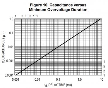
- about C7, is that a problem if we choose a 0,01µF in order to have a very short reaction, so better protection ?
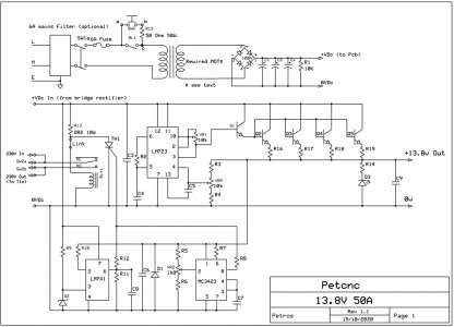
- you mention on the compenents list C8 capacitor. However C8 is not printed on the schematic :black eye:
- R1 rule is only to discharge big capacitor ? So if I have 24V fan connected to Cx capacitors, I assume I do not need R1.
- is that good or bad idea to increase to 6 x 2N3771 ? (with 60A power) It would decrease the heat provided by each transistor... But, is there an impact to Q1 and R16-19 value ?
Again, thanks for your help

Question 1: No problem! If you consult the datasheet of the MC3423 I.C. you will se the next table with capacitor values and time delay
C8.jpg
Remark 1:
You are the first one that notised this error in the schematic! Well done! here is the correct one.
NewSchem v1-1-300.jpg
Remark 2: No need for the R1 if you have the fan connected to the capacitors.
Question 2: Although I do not see a problem in increasing the number of transistors, I think it is an overkill as the four transistors can provide 4 x 30 = 120 Amps peak current! the transformer can give 50Amps max and the rectifier bridge can hold 100A max. So the safety margin is more than enough. If you plan to use a higher power transformer you need a higher current rectifier, more transistors, bigger heat sink, etc. you need to redesign quite a few parts!

Enjoy the journey of making it
It will be a very sturdy and reliable workhorse. My friend uses it almost daly and everytime I visit his shop he thanks me for it
Petros
 
Thanks a lot for the exchange !

I will build this power supply. It's exactly what I need, 50A & 13,8V with security. So I want to understand as well as I can ;)

Wonderfull the MC3423 table, thanks again, so I will put a 1nF and will check during tests.

My only goal to put more power transistor is to decrease the heat per transistor. Because I assume that if I put 6 x 2N3771, the heat will be lower than with 4. Do I'm wrong ?
I already have a 1000VA toroid transformer 17V, so 59A max.

I keep in mind to buy from a serious supplier the power transistor !

Best regards
:merci:
 
Back
Top