Acer 1440g help

tertiaryjim

Active User
H-M Supporter Gold Member
Joined
Mar 3, 2014
Messages
634
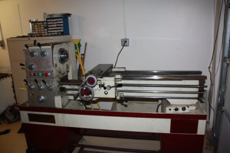
Have a couple problems so far though I've only just started working on it.
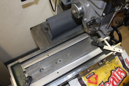
First, the gap seems to have a soft foot. What surprised me is that the bottom of the gap and the seat were completed with a disk grinder.
Thought I could expect more from Acer.
I have yet to fully re-install the gap so perhaps no change will be required, however, could anyone tell me if they've seen this before and what is the procedure to correct it.
My other problem is more of a decision I'm reluctant to make.
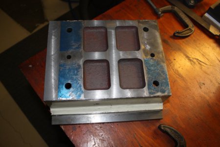
Here is the bottom of the saddle before I've touched it.
IMG_0417.JPGNice job Acer! We've got at least 90% contact. NOT!
Well, I can deal with that though getting the saddle set square to the spindle is a try and true effort till it's rite sorta thing with me.
Took about six adjustments on my little lathe till it was rite.
The real problem/decision is that the saddle is about 19 thousanths high on the inboard side. Yea, it's about 0.002"/ inch from rail to rail.
Now that I have my little mill/drill cutting square and flat. I could machine the majority of the material and scrape it in. Just not certain if it's worth the effort.
Would like your input of the pro's and cons.
IMG_0416.JPG
 
johnnyc14 had a nice write up back in '14 about his rework of the Gapbed on his CanTec 1440. Perhaps he'll chime in here.
 
Took time to think about it and realized the carriage will have to be machined and scraped. Operationaly it will make a difference. Since I'm working on it I might as well do it rite.
As it will be referenced from the cross-slide I've started scraping that in.
Also got to do some more reading of Connelly's book.
 
You need to get the saddle square to the bed. and then make the head that rotates on a pin under the head straight to the bed.
The saddle needs to be .0008" / 12" out of square as a matter of fact so it faces so the part is lower toward the center of the shaft. Also the spindle needs to point toward the operator .0003 to .0008"
and this is on a EE Monarch
Look at minute 9 and then around 30.
 
Thanks! I'll check out the vids to see what can help me.
Was considering clamping bars to stress the removable gap piece and placing it in the oven for a few hours.
May still try that.

Watched the vids and all I can say is " OH! Why didn't I think of that? Thanks again.
 
Last edited:
If there is a big gap you hay want to fill it with moglice and wax release the smoothest side.
 
The gap section is warped and having to make a choice what to do with it I worked it till three corners can be shim'd and the 60 deg rail will line up.
The flat rail will match at the mating point but it rises 0.005" at the headstock.
Checked it out with a scraper and it can be scraped
Will epoxy bed it and add cast iron filings. The epoxy allows up to 50% metal additives by volume.
When complete I can scrape it.
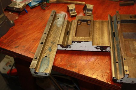
This shows the bottom of the removed gap with only three corners on plane.
Also had to open three of the bolt holes as they didn't line up.

IMG_0431.JPG

The cross-slide was rather bad and after wasting a lot of time scraping it down, thinking " Just a bit more" , I put it on the mill and took off another
2.5 mills. As the top of the slide isn't flat I set it up with two points under the compound end so the compound and dovetails will line up and a center point on the other end.
That got most of the low spots. In all I removed about 6 mills. Will now have to determine if the gears will mesh OK.
Seems ACER left a rather large backlash in some of the gearing. If it won't work I'll do as Richard suggested and go with moglice.
Still have to scrape it in but it should go much faster.

IMG_0432.JPG
Sometimes remembering bad things is good.
While scraping this I remembered that I had created an error doing my other lathe cross-slide.
I mostly moved it length wise when blueing and ended up causing the ends to be low or a convex surface.
Just the other day I was blaming it on the casting but didn't remember the real cause of the problem " me" at the time.
 
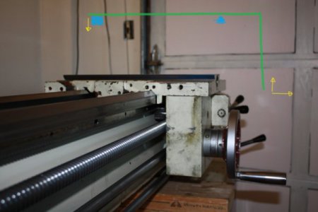
Took a good look at how the feed screws line up to the gearbox and what will happen if I lower the inboard side of the saddle.
After watching the vids that Richard posted I did a good check and found the inboard of the cross-slide is 0.024" high.
The length of the cross-slide is 15" however, the OB end sticks out 4 5/8" past the V-way which acts as a pivot.
As I lower the IB the OB will pivot up almost 1/3rd that distance.
If I drop the IB side 0.003" the OB side will rise almost 0.001" for a change of almost 0.004"
0.024 divided by 3 =8, 8 x 2 = 16
So the IB side will have to drop about 0.017" to level the saddle.

IMG_0434 mark - p.jpgAdded a little paint with arrows to show how the gearbox will lift up and move to the OB as the IB is lowerd. This will work for me since I found that will better line the gearbox up with the feed screws.
 
What the heck are you talking about OB and IB..?????????????

Before machining anything off use some plactic shimstock and slide under the low side/end until you have it within .001 to .002. Then you will have to scrape off or machine off that amount on the opposite side of the shimmed side. Trying to use math has scrwed up more machines. The shim stock is so much more accurate.
 
Back
Top