adding an iGaging Easy-View DRO to a LMS3990

ARC-170

Jeff L.
H-M Lifetime Diamond Member
Joined
Oct 17, 2018
Messages
922
So I've seen quite a few threads on this on this site and others and it seems fairly straight-forward to add DRO's to the 3 axes on this machine. I've found threads for this particular DRO on other mills and this mill with other DRO's, but not one of this exact set-up. I'm having issues with my browser (too many re-directs when I click on links in posts, which hasn't happened before, and I have to clear my cookies, but this is not working), so maybe that's why, but in the meantime any links would be appreciated.
Some of what I've read make it sound complex, when it seems to be easy. So, before I begin, I thought I'd post and see if I'm missing anything. Once I get this installed I'll post up pictures and describe how I did it.

I have the iGaging Easy-View DRO's.

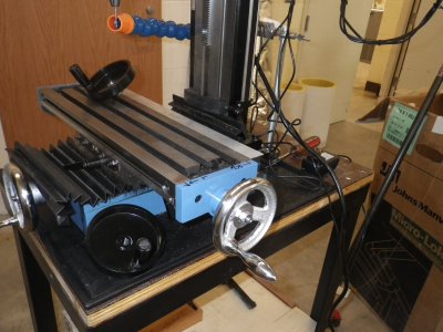
1. This is the DRO for the y-axis mounted on the left side of the base of the machine. Is the angle of the mounting bracket an issue? Some posts mentioned that they made brackets to compensate, but I don't see why it matters if it's at a slight angle.
2. There are tapped holes on the bed; I thought I would just use one of these for the read head. I might have to drill and tap another, though. Thoughts?
3. Can the cord go down as shown and have the reader still read in the correct direction or does it need to go up?
DSC00007.JPG

4. This is the X-axis shown from the back. I thought I'd drill and tap holes in the end cap or bed for the mounting brackets. Does it matter?
5. The only issue I can see with this is I got a 12" travel gauge but might need a longer one.
6. Can the cord go down as shown and still read in the correct direction?
DSC00008.JPG

7. This is the proposed Z-axis mount on the column. I thought I'd make a little bracket to mount the reader to the milling head, which would require drilling and tapping some holes.
8. Can the cord come out on the user side/front?
DSC00009.JPG
9. Do any or all axes need a cover to keep out chips and swarf?
 
The Y axis wire is fine if it comes out touching the table that way but I highly recommend buying some wire tubing to protect the new DRO wiring.
The slanted slider may be fine but I would not do it that way, instead I would screw both ends firmly to the body and instead, make an "L" shape bracket and bend the long end of the bracket to the desired angle. may need two tapped holes total.

X axis: l installed mine on the back side of the mill bed , when you eventually attach a vise to the mill bed , the back end of the vise can and will touch the column (when installed parallel to Y axis), you'd need to be aware of how you position the reader so it would work with a vise installed on the bed, you need to position the reader in such a way so the vise does not hit /crush it when Y axis is at full extension.

Y axis: it doesn't matter how the wire comes out as long as it is inside the wire tubing I recommened, it'll be protected, BTW, a bracket is also needed.

When ordering this type of DROs, it is a good idea to buy 2"-4" longer than you actually think you need, and then cut them to the length you like,. cove all the slides as much as you can since you are dealing with oil and all sorts of lubricant, way oil , before you know it all the surfaces will be covered with oil, the more protection like covers, (plastic or aluminum) will minimize the frequency of cleaning them.
 
9. Yes, you need to keep swarf out. And especially cutting oils/mist coolant, they will confuse the display.
If you plan to use a TOUCHDRO board in the future then also ensure the Scale is electrically isolated from the machine frame. Motor start spikes will cause issues.
 
a section of thin aluminum angle stock and few small tapped holes make a good cover for the reader..
 

Attachments

  • IMGP0020.JPG
    IMGP0020.JPG
    2.2 MB · Views: 336
Just an FYI, based on my experiences with a slightly older set of remote reading igaging scales on a Sieg SX2 mill. I had a lot of noise problems, with jumpy/erratic readings when the motor was running. One of the improvements (although not 100%) was to electrically isolate the scale from the mill. To address this, some have wrapped electrical tape around the end(s) of the scale where the provided metal clamps attach. I didn't find any plastic mounting brackets that are commercially available so I made some from Delrin. If you have a 3D printer there probably is a design already out there for that.

I also soldered bypass capacitors between Vcc and Ground inside the sender unit, put shielding braid around all the connector wires and added additional ground connections to the scales (this last step was the one that pretty much eliminated my noise-susceptibility problem). The other steps provided incremental improvements so I don't know if the additional ground connection was all that's needed or not.

Hopefully newer versions of these DROs are better w/regard to electrical noise susceptibility!
 
the EZ views I put on my 3990 10 months ago have been solid,, no jumps or glitches,, no special mods. no special mounts..
 
The electrical spike problems show up when using these scales with TouchDRO controller. By themselves using the included displays they work fine without isolation.
 
That wasn't the case for me, I was using the igaging displays & seeing the noise issue. I know of several other folks who had similar problems. I suspect that the aluminum scales are more problematic for that generation of DRO -- there's a sliding contact inside the sensor box, and aluminum is notorious for forming an insulating oxide skin. The stainless steel scales will be much better in this regard. I'm planning on putting igaging DROs on my mini lathe and will get the stainless steel scales for that.
 
I'm done. Took about 35 hours or so to design and make the mounting blocks for all 3 axes on my mill.

Here are the DRO's mounted on a bigger plate. I traced the original and cut mine to fit more readouts. I just need to paint the galvanized sheet metal. I'm waiting for warmer weather.
DSC00015.JPG

Here is the x-axis (L & R as you are facing the mill). The mounting block is behind the reader unit. I bolted it to the saddle using two existing holes. I had to remove the table to get the bolts attached. I used some "L" channel for a cover and mounted the rail and this cover using the same screws at the ends of the table:
DSC00012.JPG

Here is the y-axis (fore & aft as you are facing the mill). I made a mounting block with a 2 degree angle in it to match the casting draft angle. It took a little trial and error to get the exact thickness needed so the rail didn't flex. I attached it with just one bolt to an existing hole in the saddle.
DSC00010.JPG

Here is another shot of the y-axis. I made this so I had the full range of travel:
DSC00011.JPG

Here is the z-axis (up & down as you are facing the mill) and the cord management for the wires at the top. I used the existing hole for the height indicator (which I removed) and had to drill and tap another one for the other bolt. This also took a little trial and error to make the block fit so the reader rail didn't flex. I left the height scale, but could have probably removed it. I wanted the cord on the reader to clear the electrical box on the back, so I had to raise it off the surface anyway:
DSC00013.JPG

Here is the cord management. I used some spiral tubing to wrap the wires and a few wire holders that I mounted on the electrical box on the back using the existing screws. I did have to drill and tap a hole for a wire holder in the column base.
I'm wondering if I should use the split tubing instead?
DSC00014.JPG

I wanted to add a cover for the y-axis, however this was the first axis I installed and as I used the mill I found it didn't get as dirty as I thought. The wire comes out the top, but I thought I might eventually raise the mill on blocks, which would allow me to flip it and have the wire come out the bottom. I didn't want the wire binding or rubbing on the table.

I measured the mill and drew everything in CAD. I only had to change a few dimensions to make everything fit. I'm happy to share them; just let me know if I should post images of the drawings here.
 
I used split plastic tubing on my DRO setup. The tubing came with an "unzipper" that made it easy to get the cables into the cover. It would have been much more difficult without that little thing.

It sort of depends on how long your cables are. A long cable with the spiral tubing could be a pain. It's not the cable itself, it's small enough to slip inside, but the connector on the end that's the problem.
 
Back
Top