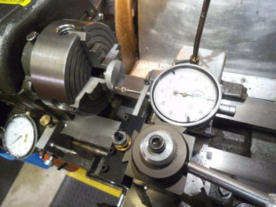
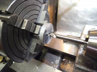
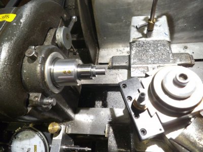
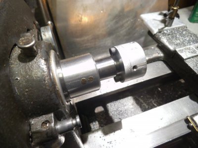
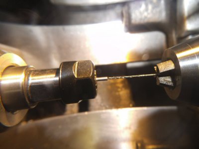
Adjustable tail stock chuck....things learned in this section of H-M

David S

Active User
H-M Supporter Gold Member
Joined
Nov 18, 2012
Messages
1,352
Hi guys,

A bit of a background. I am a hobby machinist with NO formal machining training. I started in the 70's with a Unimat lathe/mill kit to make RC boat model servos, gear boxes etc. I got a number of accessories for the little machine and did some nice work with it. Then as I moved into restoring old small engines, I got an opportunity to purchase an Atlas 618 from a retired machinist who purchased it new in 1949. And this has been my work horse for the past 4 decades.

When I retired 7 years ago I decided to repair old mechanical clocks for people. My main go to machine is my Atlas 618 and for milling I am using a circa 1970 Jet 13R bench top drill press made in japan, with a chinesium X-Y table and an old craftsman tilting vise.

I knew that I needed to learn more about machining, so happened upon this forum, after determining that some of the others weren't going to work for me. Since joining here I have learned a lot, and have enjoyed the open discussions in this section on various topics. My first experience was seeing someone make a larger cross feed dial for their lathe and knew right away my Atlas needed that big time. I made one a few years ago and posted in the Atlas section the results of my project. Next I was introduced to LMS and the A2Z QCTP for the Atlas 618. Finally I got rid of the dreaded lantern tool post and things were so much more enjoyable.

Which brings me to this thread. Frequently in clock repair I have to replace a pivot that is either broken or severely worn on the arbor of a gear. This means that I will have to drill a Ø 0.7mm hole in a Ø 1.5 mm arbor in order to insert a new one. Unfortunately my lathe tail stock chuck is not aligned to that accuracy. Now I see that companies like Sherline offer adjustable tail stock chuck which seems like a tail stock taper with flange mated to a chuck with a flange by a couple of screws with clearance holes so you can bump it around to get alignment and then tighten the screws.

I wanted something that was more controllable in order to adjust the X and Y axis, similar to the jack screws to adjust the X alignment of my tail stock. As I started to progress I realized that I was doing things differently than I had in the past due to information learned here, so thought that this would be a good section to "give back".

The material that I had on hand is a cut off of Ø 1.25" 6061 aluminum rod x about 2" long, and some Ø 0.5" 12L14, so this is what I am trying to squeeze in. The fasteners are 8-32 set screws and SHCP screws.

The approach will be to use the two flange method, but with rectangular features on their face that will mate with a coupler with a square centre hole. The idea is to have each flange tuned to slide in the coupler in each of the X and Y axis.

The next post will start the pictures. I hope this is ok to post in this section.

David
 
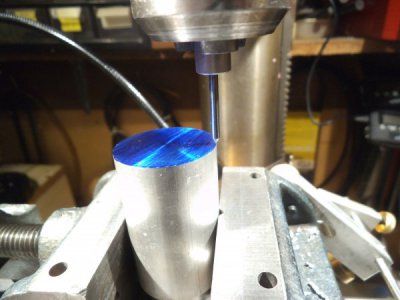
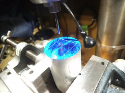
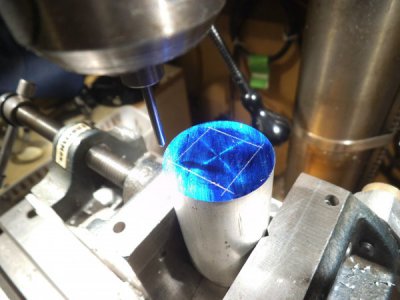
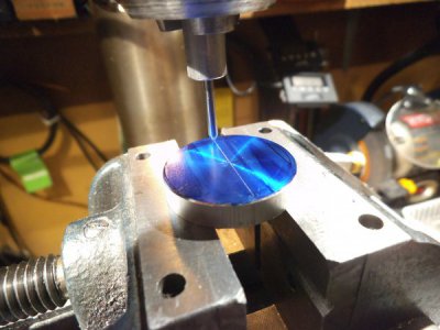
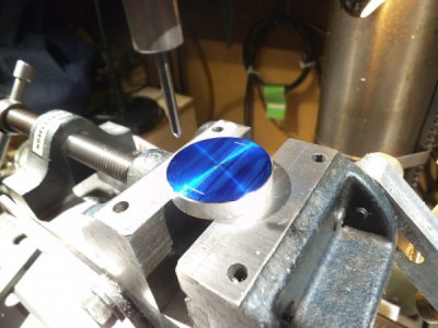
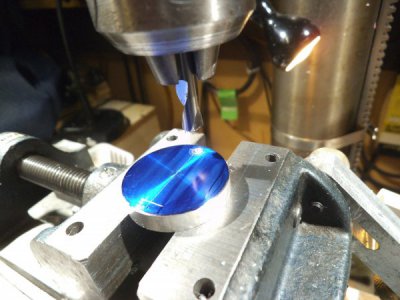
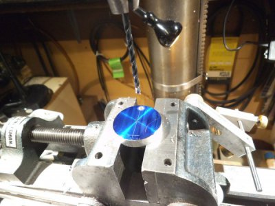
The first step is to mill out a square hole in the coupler which is about 0.5" thick. After I had started making it, I realized that I didn't photo how I layout out guide lines so the first couple of pics are just showing how we use the X-Y table to first find the edged and then using a my spring loaded tap follower as a scribe to make the lay out.
laying out the squares _ finding edge.jpglayout third scribe.jpglayout complete.jpg

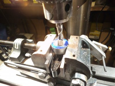
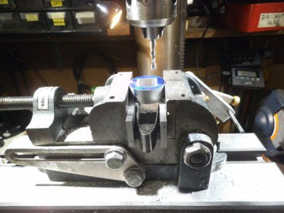
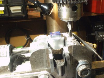
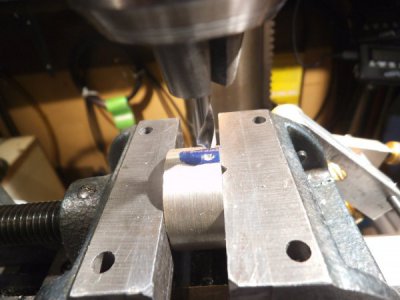
The coupler is turned in the lathe and faced both sides parallel and a .625 hole drilled in the centre to remove most of the material. To make the hole square on my set up I found it best to use a large diameter end mill and nibble away by plunging > moving X (or Y) plunge..> repeat until it is roughed out. Then side mill around and follow up with more passes with a smaller diameter end mill.

rough milling square coupling..jpg and now the smaller end millfinish milling square coupling,..jpg

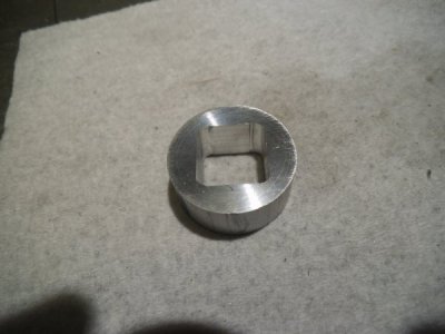
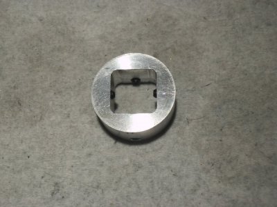
And the finished result.
square coupling finished.jpg

Next we have to make the mating flanges. And because my screen is getting busy, I will do it in the next post.

David
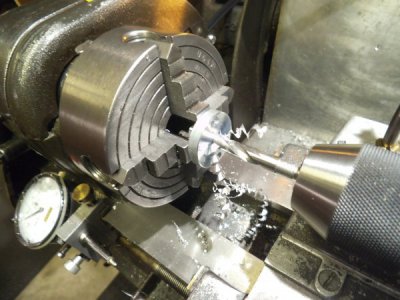
 
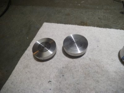
The mating flanges. One will be called the MT1 flange and the other will be the chuck flange.

The layout will be similar to how the coupler was laid out, however this time we are milling off the sides. We are using the remaining stub aluminum rod and will machine the two rectangles on opposite of the same rod and will be cut off later in order to have more material to hold on to.

milling the MT1 side flange.jpg The next steps are just to turn the rod over and mill the rectangle on the opposite end. That is boring..I mean milling, but not interesting.
So the next step is to separate the two flanges. We want to save as much material as possible.. Normally I would cut this off with a hacksaw, but I don't want to waste material facing off the hacksaw cut.

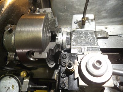
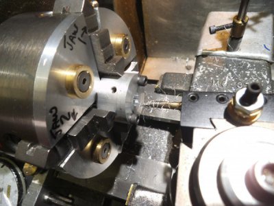
So we are going to part it off in the lathe. Let me set this up. This is a very deep cut. My parting tool is 0.040" wide and double ended. One end is ground on a slight angle so that when I part something off the "tit" is left on the workpiece in the chuck. However this can cause a thin parting tool to deflect. The other end is ground square to the end. This is the end I am using and honed it well.
Here is our set up.
Make absolutely sure the parting tool is perpendicular to the work piece.
Grind tip square to the tool.
Move as close to the chuck as possible.
Lock Z axis, rotate chuck to verify clearance.
On my lathe jack shaft I can set to minimum tension in case of a crash will disengage.
This is going to be like "peck" drilling. Set the parting tool over hang to about 0.3"
advance the parting with lots of WD40 fluid.
Next advance tool stick out by another .25", keep parting and clearing frequently
And finally with another .25" stick out it should be parted off

parting the two couplers in half.jpg and wow this impressed me.both flange surfaces after parting mating parts.jpg

So now back to the coupler. We have to put the taped holes in for the jack screws.

The holes have to be perpendicular to the internal flats, and on the centre ( approximately)

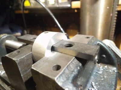
Again I forgot to show how I located the coupler parallel to the internal flat so will show that here.
Use a parallel to locate the coupling lightly tighten vise, remove parallel, tighten.

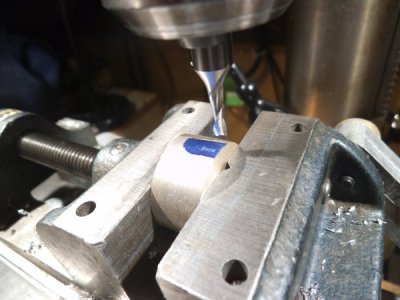
using parallel to locate coupler on flat_ example only 2.jpgto find the centre of the coupler to the accuracy for this project. take an end mill and just kiss the top of the coupler, then with a centre point "eyeball" the location.
usning endmill to locate centre of round.jpguse centre pointusing centre point to locate top of round.jpgmy photography isn't all that good sorry.
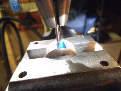
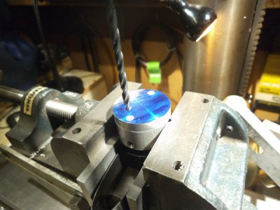
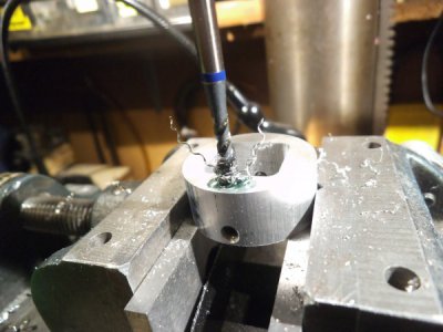
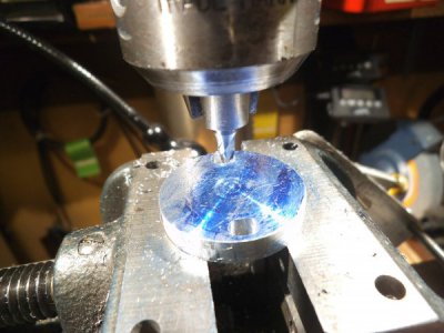
So now we have to spot, tap drill and tap the coupler. Note how the spotting bit is chocked way up in the chuck to improve stiffness. Before H-M I would have used a 60 degree centre drill...no more.
spotting drill to start tap drill.jpg
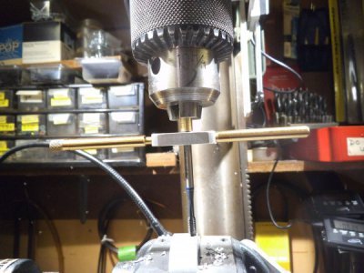
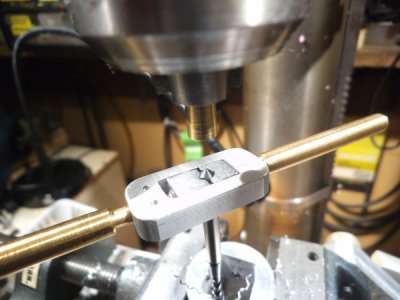
The tap drill will snuggle nicely into the spot, and next comes the taping operation. Another H-M learning. I now use a spiral POINT plug tap. goes right thru in one pass dry with no backing out and pushes the chips out the bottom. There is a brass rod with a small hole in the chuck to keep the tap perpendicular.
spiral point tap.jpg and here is the coupler with the 4 jacking screwscoupler with jacking screws in place.jpg

So this process is repeated for 4 tapped holes

The next post will be working on the flanges.

David
 
Last edited:
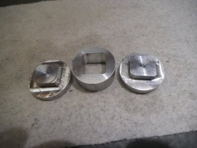
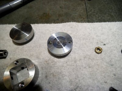
So here we are. One coupler and two rough machined flanges.
coupler and flanges.jpg
Now we have to drill and tap the flange securing screw holes. Ultimately slotted clearance in the flanges with tapped holes in the coupler.

First is to locate the flange by its flats and drill holes on the centre line. Note use the #29 tap drill first so that the flange with these holes will serve as a drill guide when locating the holes in the coupler.

chuck flange scribing 1.jpgchuck flange scribing complete for tap drill first 1.jpgchuck flange spot drilling note choked up bit.jpg
note again how the spotting drill is choked up to increase stiffness.
followed by the tap drill.
chuck flange tap drill.jpg
Repeat for the other hole and then use it as a guide to drill starter holes into the coupler, example below
MT1 flange screw holes.jpg
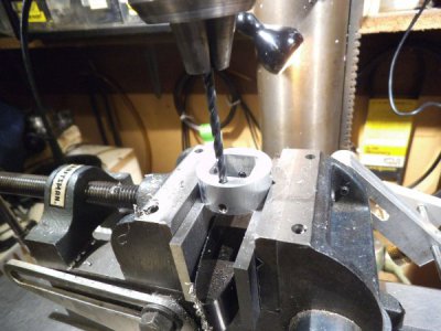
Now we have a starter hole in the coupler, remove the flange, set the tap bit to zero and drill down about 0.265" don't hit the set screws.
coupling blind holes to 262 thous deep 2.jpgcoupling blind holes to 262 thous deep.jpg

And now another H-M learning. this is a shallow hole that we need to tap. Using a spiral FLUTE tap, this time with cutting juice, but one shot all the way down.
spiral flute tap guide centre.jpgspiral flute blind hole tap.jpgok folks that right there is "angel hair" those nice chips coming out of the blind hole rather than binding up. Awesome and another great learning from here.
This process is repeated for all of the four flange mounting holes.

Now that the coupler is tapped we need to make the clearance slots in the flange to allow lateral adjustment.

Next post.. Nothing spectacular but should include it I guess.

David
 
"watching". Thanks for sharing.
-brino
 
Now comes the accurate stuff.

We need to make holes in the centre of the flanges to mount the chuck arbour and the MT1 tail stock arbour. Must very carefully centre the flanges and drill / bore the hole.
chuck flange centering for through hole.jpg Chuck flange parallel facing 2.jpg

In the old days I would use a centre 60° drill for the starter and then step drill up to the final size. Now we use a spotting drill and then a 5/16" stub drill in one shot.

chuck flange spotting for through hole.jpg look at the nice chips on both fluteschuck flange 5-16 in one shot for through hole.jpg

Now just to be sure the hole is true we take a few skim cuts to increase the diameter to about 21/64" with a small boring bar as shown with the other flange.

MT1 flange boring arbor hole to size.jpg

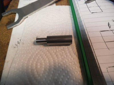
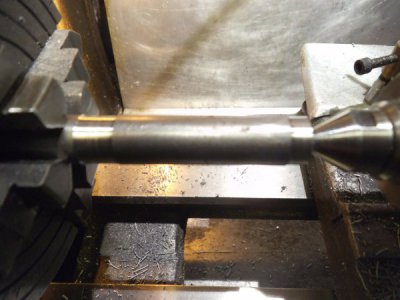
We need to make an MT1 arbour for the Atlas tail stock to attach to one flange. We don't have a taper attachment, and I don't like messing with the tail stock to offset. Fortunately the Atlas compound travel is 1.75" which is just enough to make a MT1 arbour.
Before setting up for the offset, put in a piece of stock supported by the tail stock and take a couple test cuts to verify alignment.
test cuts first to check tailstock alignment.jpg
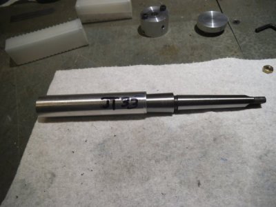
To set the compound we are going to use a JT33-MT1 arbour as a pattern. Adjust compound until it runs parallel to the pattern

J33 mandrel for support JT33-MT1 pattern.jpg setting compound for taper small end.jpg setting compound for taper large end.jpg

Arbour will be made from 12L14, must leave a stub on the small end so that it can auto eject when the quill is fully retracted.
Also note that about 0.6" of the centre of the arbour was relieved by about 0.010" to ensure that the taper seats more near the ends.
turning 12L14 MT1 adapter 2.jpg
remove arbour and using a MT1-MT2 sleeve, mount in headstock and turn mounting flange register
MT1 flange arbor turning to final diameter.jpg snug test fitMT1 flange test fit in lathe.jpg

MT1 flange mounted to arbor.jpg

David
 
Good job! I also do a lot of pivot work. It’s common for me to drill a 0.008“-0.015” hole. I commend you on your capability to drill a 0.028” hole on your size/type lathe. People that have not done said task must understand the finesse involved. This topic is not new and has been challenged since timepieces have been around. There are sooooo many ways to do it. Yours is another great addition, thanks for sharing…Dave
 
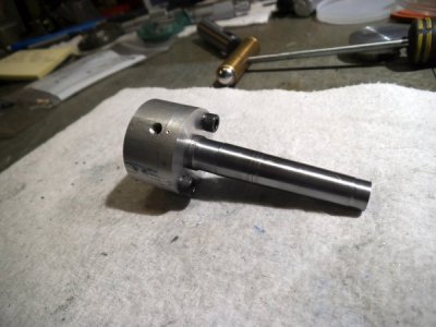
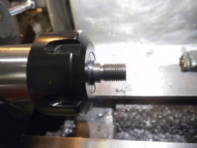
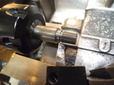
The small chuck has a 3/8-24 female mounting bore and an accurate register. The mating arbour is made from 12L14 and threaded with a die. Since this is not a heavily loaded joint, and to reduce the threading effort the threaded portion will be turned down to just over the minimum major diameter from the chart.

First turn the flange register section longer than it needs to me so it can be held securely in a collet.
Chuck flange arbor starting.jpg
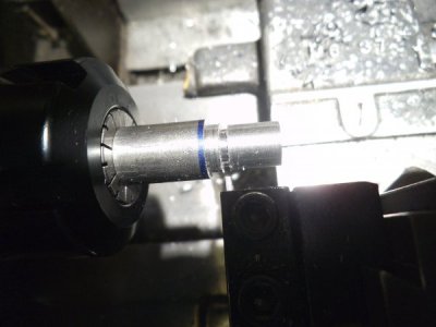
Hold in collet to turn the chuck register. On the right is the thread diameter, next the thread runout undercut and on the left the register shoulder rough machined oversize. Threading takes a lot of torque so hold the part by the large non critical diameter in case it slips in the collet.

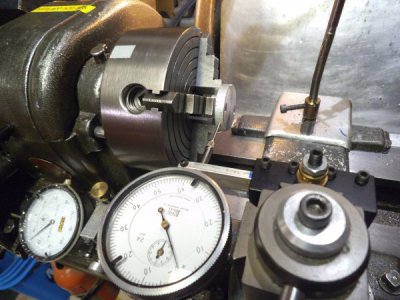
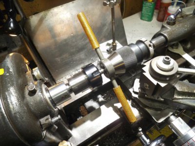
Open up the tailstock chuck so the face presses against the die stock. Note air line hose on die stock handles to prevent marring carriage or ways. It is often hard to start larger dies but this allows one to put considerable pressure on the die to start it. Turning is done by hand using wrench on the collet body.
chuck flange arbor thread runout undercut.jpg chuck flange arbor threading 3_8-24 chuck to keep square.jpg chuck flange arbor threading 3_8-24 complete 2.jpg
Back to the smaller collet locating on the flange register and turn the final chuck register.
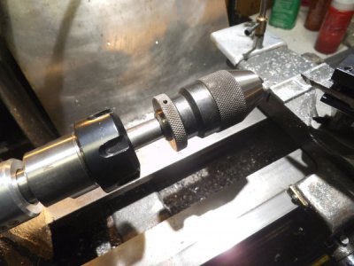
chuck flange arbor turning final resgister.jpg Chuck flange arbor chuck fit up final.jpg

The fit ups for the arbour to flanges is a snug hand fit. A press fit was considered but felt right or wrong that perhaps there would be some distortion during the pressing, so we are securing them all with loctite 608.

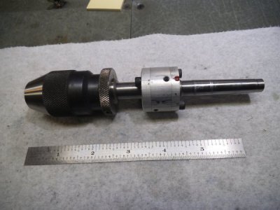
FINAL ASSEMBLY.jpg

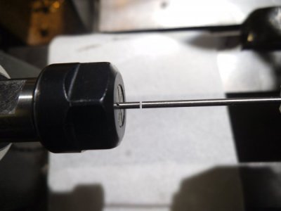
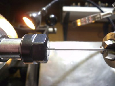
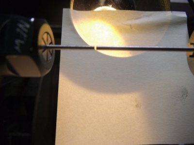
And the moment of truth. The jacking screws were all adjusted to centre the collar using the "finger nail" test for fit up. Then a Ø 0.059" gage pin was placed in a collet in the headstock, and a Ø 0.060" gage pin in our adjustable chuck and bring them together.
Big time disappointment ....in a way. I have not adjusted anything else and looking straight down in the Y axis with the best focus I could get, here is what I see! The X axis alignment is close to perfect. Even a blind squirrel finds a nut sometimes.

alignement straight down ie X axis  right on.jpg

Fortunately the Y axis did require alignment.
alignment Y axis as assembled before adjustment 2.jpg after alignmentalignment Y axis as assembled after adjustment 2.jpg

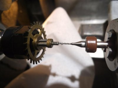
And as a final test, lets put it to work for its intended purpose. Here we are drilling with a 0.7 mm carbide bit
1_5 mm arbor with 0_7 mm carbide dril  right on centre.jpg and a test with HSS Ø 0.025" bit1_5 mm arbor with 0.027 inch hss dril  right on centre.jpg

Wow this is a long thread. Perhaps it should be moved else where. It really is about so much that I have learned from everyone here and how it has influenced how I go about making stuff. By being careful I am actually impressed how with my old Atlas 618 and a drill press mill sort of, this turned out so accurate and will be useful in my clock repairs going forward.

David
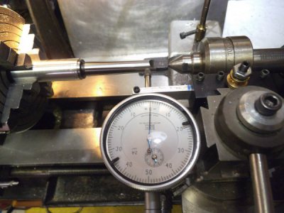
 
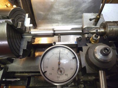
I did the same thing a dozen years ago. for my Atlas/Craftsman 6 x 18. At that time, I was drilling .008" holes in stainless and concentricity was very important. I made mine from brass and mounted a 1/4" keyless chuck.
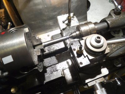
At the same time, I made a Set Tru style backing plate for the #" 3 jaw chuck.
I also added an adjustment for angular runout. It's a bit tedious adjusting as there are three points instead of four and the radial and angular adjustments interact. but the chuck is adjusted for .0002" TIR at the chuck and .0008" at six inches.
 
Back
Top