One more comment on dry ring testing. I have seen (on a Hodson radial actually) where the builder positioned a vey bright LED flashlight down the bore, maybe he made a holding/sealing gadget, can't recall. Apparently any ring eccentricity/fit will leak the tiniest amount of light & it did correspond to when he had a so-so ring from pressure testing. These were shop made CI rings using the Trimble method so any finishing or heat set irregularities were quickly spot checked using this method. I guess one could position the piston at different positions of the bore too but upper TDC area is where it mostly counts. The problem with measuring ring gap only is its a borrow method from FS engines where the rings are lets call them perfect & the only variable is bore/condition so gap is a proxy for fit. But when we make our own rings in the shop, especially small ones, new factors can enter the equation. I'm not sure how the oil control rings would be introduced into this, maybe he did compression only or a second test? I'd have to check the post.

-
Welcome back Guest! Did you know you can mentor other members here at H-M? If not, please check out our Relaunch of Hobby Machinist Mentoring Program!
You are using an out of date browser. It may not display this or other websites correctly.
You should upgrade or use an alternative browser.
You should upgrade or use an alternative browser.
Ageless 9 cylinder radial engine build thread
- Thread starter starr256
- Start date
- Joined
- Apr 7, 2018
- Messages
- 131
Nice to see a simple volume equation. I made the gears that are called out in the design. My problems were not with the gears, but with the housing. First the arbor shafts need to EXACTLY placed. Even a couple of thousands off and the problems begin. Second, the gear housing need to be no more that a couple of thousands larger the OD of the the gear. The greater the diameter, lower flow. Third, the floor of the gear housing has to be FLAT. Can't use a counter bore or a center cut endmill. So you need to single point bore the housing. Fourth, the the gear housing and the arbor hole have to be CONCENTRIC. EXACTLY. And finally, the spacing between the gear and the rear bearing can't be more that 1 to 2 thousands. Exactly. And remember that the arbor holes are mated with the rear bearing. I made a bunch of gears trying to address all these issues, failure was my results. After a number of tries, I made a test pump using gears I made to spec. Simpler setup. Cheaper to control things. With this setup, I got much better results. One thing I would suggest is to make a jig such that the arbor holes and gear housing holes can be turned on a lathe with the hole pump housing mated together. I used a boring head on the mill and found the accuracy was just not there for me.I'd really like to know more about your oil pump because that is in my future on next engine. Did you cut regular involute gears? This topic came up on model engineering forum. I plagiarized a spreadsheet from another builder so I could evaluate metric/module gears vs imperial because I can get them easier in the smaller sizes. We are still sorting out why the spreadsheet seems to indicate high flow volumes, so more to come on that front. But he took a video of his little pump & it is certainly squirting a lot of oil for such thin gears. I did read that technical paper you referenced.... along with about 5 others. Unfortunately its like a jigsaw puzzle, they specify some parameters but not others. There are Hodgson builds on other forums, I'm sure the pump was discussed. I can find links if you haven't already seen some builds. Here is where I'm at right now with my spreadsheet. the governing equation is actually very simple but like I say, something seems amiss so we need to get back on this.
Yes, the oil pump was a challenge. Learned a lot, skills improved and happy to move on.
All doneThis were iam at
- Joined
- Aug 6, 2015
- Messages
- 3,861
Photos and the video are not showing up….All done
")
- Joined
- Apr 7, 2018
- Messages
- 131
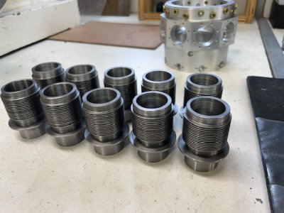
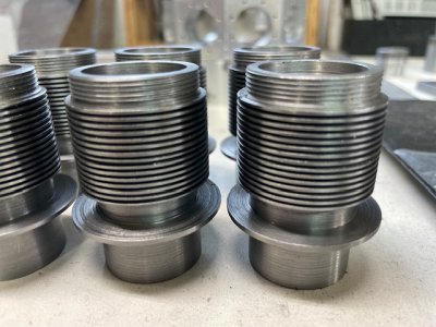
It has been a while since I reported any progress, but the time was not completely devoid of machining. So, allow me to present a couple of photos of the results of the eight months. Ten cylinders, that's it. I will now document the issues I had with these ten cylindrical chunks of metal. First you will note that the gap between fins is 0.032" wide and 0.125" deep. The first attempt was to grind a cutter to do the job. My eyes, hands and temperament was not up to the job. After many, many tries, I found a solution in a 0.032" cutoff blade with a special holder. Next problem was that the motor of the lathe was not producing enough torque at the low RPM (~100) that I wanted to run at. I managed to get the fins cut using a wonderful cutting fluid. This stuff is dark, thick and smells really bad, smoking or not. But it worked great. Next issue came with the 1 1/4-24 treads. The lathe's low torque at low RPM meant that I just could not cut the threads safely (I am sure the machinist down the street could, easily. But that ain't me.) I found a solution with a 2HP BLDC motor and controller. The old motor was a brushed DC motor with hall effects and a special controller. Aside from doubling the HP, there were two cool features with the new motor/controller. First is a parameter for has fast the controller will try get the motor up to specified speed. The second is a parameter for braking. With this, the motor stops on a dime, meaning single point threading is a breeze. One of the enticements of this project was to get a feel for the process of making many copies of things. The manual suggest that you should add a couple extras when making multiple copies. I probably should have added even more. I found with each operation it took me a couple of iterations to get in a "groove" and get things done efficiently and with repeatable results. The next part is the cylinder head. This will trruly be a challenge.