- Joined
- Jan 1, 2014
- Messages
- 233
Have been working on a model engine which was inspired by watching a Chuck Fellows You Tube video titled “Compressed Air V8”. I wasn’t trying to make mine small or refined as his, or of aero design, but have used his idea as described of a basic V-8 layout with a central rotary valve and spring controlled valves in the head.
Didn’t want it to be costly so materials at hand started to dictate the size and shape and it soon started to look like a industrial or marine engine, which was fine by me. Just wanted to see if I could make it and have it work.
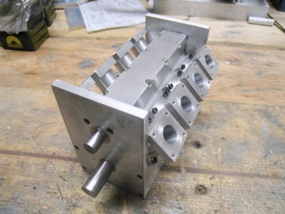
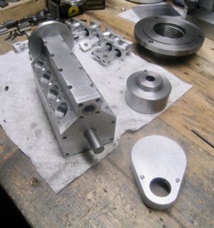
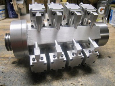
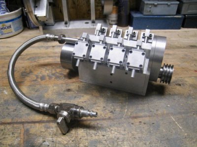
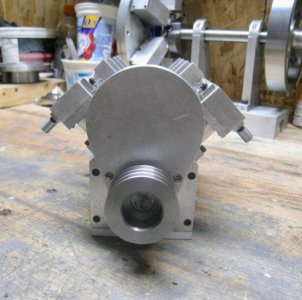
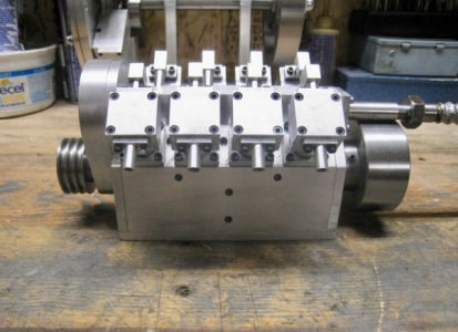
I used a 5/8” bore, 1/2” stroke and 1-1/4” cylinder spacing with 1/4” offset between banks. Thus the block is 5 1/4” OAL and fabricated from 1/4” AL plates attached to a AL 1” x 1-1/4” bar, which also houses the rotary air valve. Lots of 4-40 drilling and tapping.
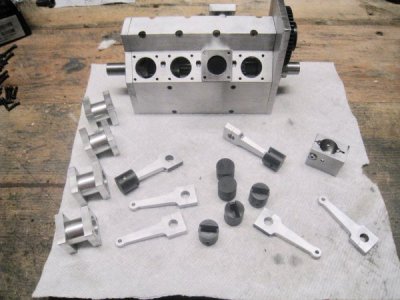
Cylinders are from 1” square AL with the centre part turned to 3/4” to make them look better.
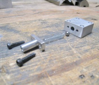
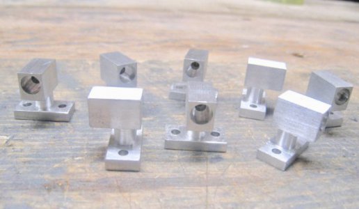
Heads were made from 1” square bar and cross drilled for the spring loaded air valve. The exhaust pipe flange holds the spring and ball in place. Small 90 degree flanges for the other side of the head plus a tube deliver the air from the rotary valve.
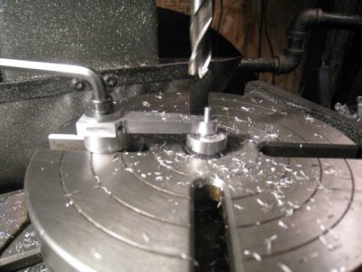
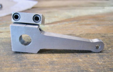
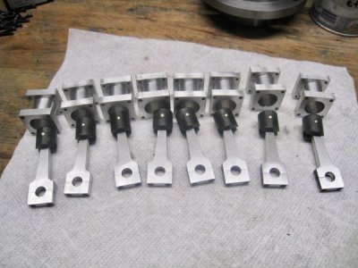
Rods are AL, 1 3/4” long, .200” thick tapered to .156” at the 1/8” wrist pin end and running on .300” crank journals. 4-40 SHCS hold the end caps on.
Pistons are Acetron (close to Delrin I think). Made a little jig so the pocket could be milled out for the rod end and cross drilled for the wrist pin.
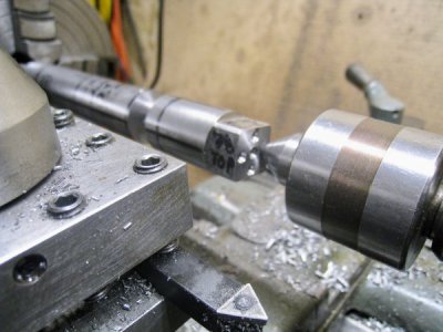
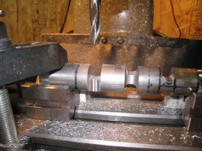
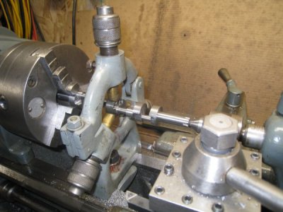
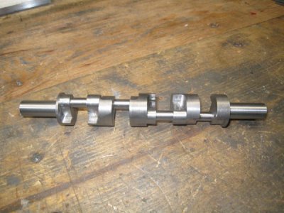
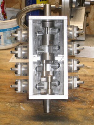
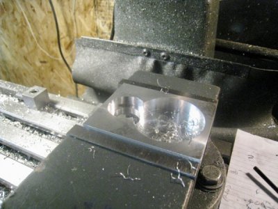
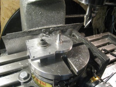
The crank is made from 1” dia C12L14 (easy machining) of cross plane design for a 4 stroke 1-8-4-3-6-5-7-2 firing order, which is typical American 90 degree V8. The crank started out 8-1/2” long with matching squares on each end. These were used for setup and control throughout all the remaining operations. The 1/4” offset centre drill holes were done on the mill. I was initially going to turn it completely in the lathe so set it up in the lathe 4 jaw, using the squares, with a .250” dialed offset. After turning one journal I realized that there was a better way to at least rough it out. Set it up on V-blocks on the mill using the square ends for control again, and ,“roughed out” the journals with an end mill “by the numbers” leaving some for cleanup, then, back to the lathe for finish turning. Went back to the mill to shape and turn the journal counterbalances, this time using the RT and tailstock and a custom “dog” on the squares for control. Finished turned the ends in the lathe and dressed the crank a bit by file and emery. It is supported by a 1/2”x1/4” long bronze bushing at each end and a 1”x1/4” wide bronze bushing in the middle.
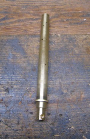
A steel sleeve with a 1/2” reamed hole was inserted into the spine to house the brass rotary valve. !/4” pockets were milled into the spine at 45 degrees on cylinder centrelines to accept the air pipes.
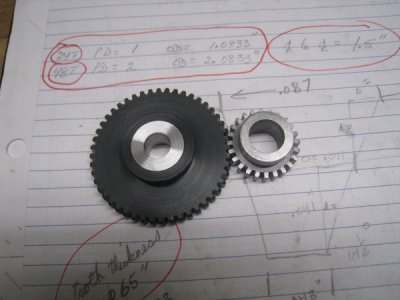
Once the motor was assembled a homemade degree wheel and a DI were used to position the crank at each TDC and a hole was then drilled into the rotary valve. Overall valve timing is adjusted by moving the timing gears for the best effect. Noticed right away that the motor didn’t have much oomph as a 4 cycle so drilled the extra holes to convert it to a 2 cycle. The “intake & compression” parts of the 4 stroke cycle were just drag in this situation.
The motor runs from 400 RPM to 1800 RPM reasonably well on my small compressor. Air leakage is a factor some of which could be fixed but I am not worried about that, just that it works. Also, because of the V8 design there is a lot more friction to overcome compared to my 6 cyl Radial but it works, was a lot of fun to make, and certainly is good practice and experience for the next one!
Cheers


