- Joined
- Feb 7, 2013
- Messages
- 2,485
As it turned out, this was a very difficult repair. In the beginning, the tachometer was reading way too high. After disassembly, I found the bearing
inside the magnet was worn and had about 15 thousandths clearance. That I repaired by filling in the bearing with solder and inserting a .040 diameter
piece of safety wire. That helped a lot but the readings were still too high and no adjustment left on the hair spring. I increased the spacing between
the rotating magnet and the outer ring that is attached to the pointer but still reading too high and no visible way for any more adjustment. I reasoned that
if I reduced the magnetism in the rotating magnet somewhat, I may still be able to calibrate this thing. I used an electric drill with a no load speed of
1400 rpm for my reference. With a little experimentation using a strong neodymium magnet, I was able to change the strength of the rotating magnet.
After that was accomplished, it was a simple matter to adjust the hair spring to set the dial to 1400 rpm. I lost track of how many times I disassembled and
reassembled the tachometer but it was necessary because the readings would change when the steel cover was installed.
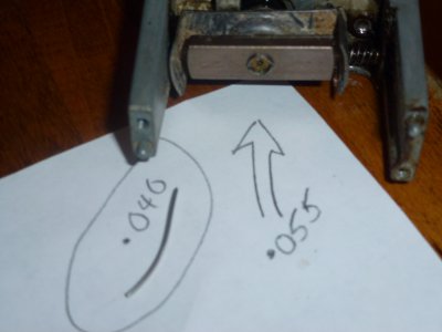
This photo shows the bearing hole measured at .055 inches and a piece of wire .040 to be used to cast a bearing with a .040 hole diameter.
Bearing clearance in this is critical because the magnetic attraction increases with a worn bearing!

Edit: I have to laugh at this photo as just below the pencil are two optocouplers I removed from a switching mode power supply
that ended up in the to be visible and were laying on the desk.

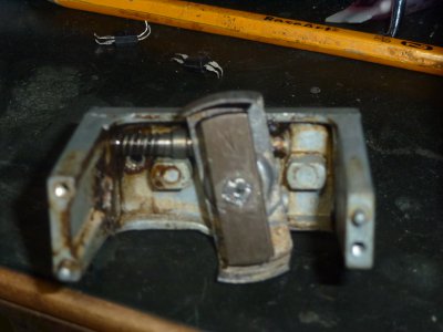
In this photo, you can see the bearing in the center of the magnet which now is .040 inches and centered in the hole. The centering took
a number of tries so that it truly was in the center.

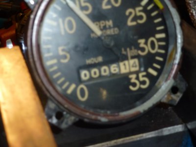
I didn't have enough hands for this photo as I had to hold the drill and take the photo with the other hand. Anyway, I did as best as I could to
take the photo as the tachometer was lightly cradled in the mill vise and would start slipping away from the drill as soon as I was ready to
take the photo. Anyhow, it reads 1400RPM which should be close because my 1/2 inch Milwaukee drill has a no load speed of 1400 RPM.
If I need to take this a step further, I will use my horizontal adapter for the mill, set the VFD to 60 hertz and use the chart for the mill as it is
a step pulley unit with speeds listed. Anyway it is working now as it was useless before the way it was. I also pretty much zeroed out the
hour meter while I was at it, not a simple task in itself.
inside the magnet was worn and had about 15 thousandths clearance. That I repaired by filling in the bearing with solder and inserting a .040 diameter
piece of safety wire. That helped a lot but the readings were still too high and no adjustment left on the hair spring. I increased the spacing between
the rotating magnet and the outer ring that is attached to the pointer but still reading too high and no visible way for any more adjustment. I reasoned that
if I reduced the magnetism in the rotating magnet somewhat, I may still be able to calibrate this thing. I used an electric drill with a no load speed of
1400 rpm for my reference. With a little experimentation using a strong neodymium magnet, I was able to change the strength of the rotating magnet.
After that was accomplished, it was a simple matter to adjust the hair spring to set the dial to 1400 rpm. I lost track of how many times I disassembled and
reassembled the tachometer but it was necessary because the readings would change when the steel cover was installed.

This photo shows the bearing hole measured at .055 inches and a piece of wire .040 to be used to cast a bearing with a .040 hole diameter.
Bearing clearance in this is critical because the magnetic attraction increases with a worn bearing!

Edit: I have to laugh at this photo as just below the pencil are two optocouplers I removed from a switching mode power supply
that ended up in the to be visible and were laying on the desk.

In this photo, you can see the bearing in the center of the magnet which now is .040 inches and centered in the hole. The centering took
a number of tries so that it truly was in the center.


I didn't have enough hands for this photo as I had to hold the drill and take the photo with the other hand. Anyway, I did as best as I could to
take the photo as the tachometer was lightly cradled in the mill vise and would start slipping away from the drill as soon as I was ready to
take the photo. Anyhow, it reads 1400RPM which should be close because my 1/2 inch Milwaukee drill has a no load speed of 1400 RPM.
If I need to take this a step further, I will use my horizontal adapter for the mill, set the VFD to 60 hertz and use the chart for the mill as it is
a step pulley unit with speeds listed. Anyway it is working now as it was useless before the way it was. I also pretty much zeroed out the
hour meter while I was at it, not a simple task in itself.
Last edited:

