And another drum switch question

L

Lordbeezer

Forum Guest
Register Today
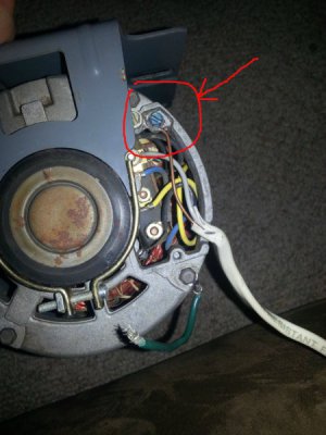
I have looked at every drum switch post here.you tube.goggled many different diagrams.its got to be simple but I give..can someone show me a simple diagram on how to hook this up.it works one direction the way it's wired.can switch red and black to reverse.tried unplugging red and black.running wires to switch.pop breaker.motor is split phase 1/2 hp 115v.switch is furnas r-22..have wired by several different diagrams with no luck..thanks..
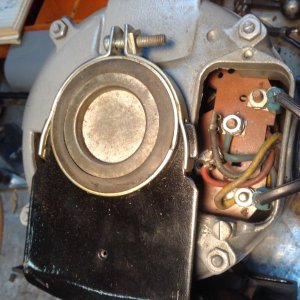
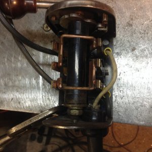
image.jpeg

image.jpeg
 
I think you may not have enough conductors in the feed to the motor. You need 4 conductor wire, 3 power and 1 ground. Two of the power wires get switched on the starter circuit. I cannot tell from your motor picture which wires are the starter circuit.

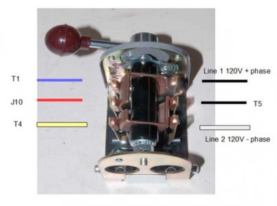
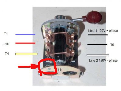
This is a picture of my drum switch. I added the coloured lines to show how my motor needed to be wired. This is the Forward position.

Drum_switch_forward.jpg
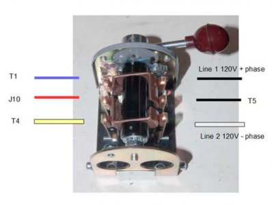
This is the reverse position.

Drum_switch_reverse.jpg
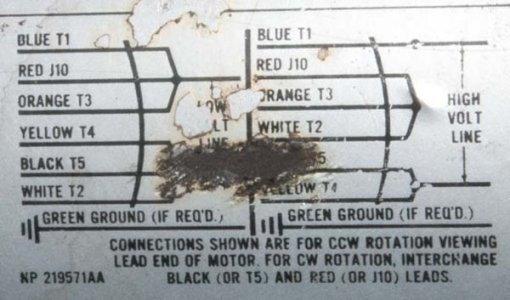
My motor at least did have the diagram to show how the wires connect.

GE_motor_wiring_diagram_terminations_only_2972.jpg

I think you first need to determine the run wires and the starter wires. The starter wires will go through the centrifugal switch.
 
Yup, there are several different ways to wire a silly drum switch. Your motor appears to use terminals 1 and 4 for run and 2, 3 for the start winding. This diagram should work for your motor, although there are other arrangements that would also work:

View attachment 227008

If the motor forward and reverse rotation doesn't match the desired handle positions, reverse the connections to 2 and 3.
Mr.Dan, I'm going to try this on my drum switch with my old Wagner motor. My question is where do I connect the Green ground wire or is it connected with an extra ground wire that's connected to the motor.... never mind, I think I just answered my own question.
Thanks, Tim
 
Yeah, the green ground connects to the motor case. There's usually a screw (sometimes colored green, sometimes not) provided for this purpose.

Like this: (ignore the hokey wiring, this is just an image I found to show the ground screw)

ground.jpg

And the ground needs to connect to the drum switch case as well (to plagiarize Dave's pic):

Drum_switch_reverse.jpg
 
Last edited:
Note that the green ground wire is for safety, under normal operation it does nothing (the motor will go without it). If the internal motor windings or terminals, or any of the drum switch live parts were to accidentally come in contact with the case(s), then the parts you touch could become live, and give you a nasty shock. The green wire conducts this current safely to ground, tripping the breaker in the process, protecting you. Never leave it out, always ground the cases of anything that has current-carrying wires inside!
 
Mr.Dan, I'm going to try this on my drum switch with my old Wagner motor. My question is where do I connect the Green ground wire or is it connected with an extra ground wire that's connected to the motor.... never mind, I think I just answered my own question.
Thanks, Tim

Tim,

Don't use my diagram. I had a complete brain fart. I just realized his motor was not the same one that I was thinking of. The diagram I posted won't work in his case, I have deleted it. Good grief.

Without seeing your motor it's impossible to tell if it would work for you either. Sorry.
 
Lordbeezer, here is the diagram that should work in your case. I hope I got to the old diagram I posted and got it deleted before you tried it! Egad....

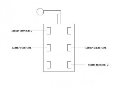
You will disconnect the red and black wires from terminals 3 and 4, and bring all 4 connections (2, 3, red, black) to the switch. This diagram does the equivalent of unplugging the red and black and swapping them on the terminals.

MotorRev.jpg
 
Last edited:
Lordbeezer, here is the diagram that should work in your case. I hope I got to the old diagram I posted and got it deleted before you tried it! Egad....

You will disconnect the red and black wires from terminals 3 and 4, and bring all 4 connections (2, 3, red, black) to the switch. This diagram does the equivalent of unplugging the red and black and swapping them on the terminals.

View attachment 227019
Mr. Dan, Thank you. I'm at work and don't have any pictures of my motor on my phone. I'll snap some tonight and post what the inside of this old motor looks like. It's really weird. There's only 4 wires and they were connected in pairs, then wired to the drum switch. The sad part is the motor ran in forward and reverse when I bought the lathe!
Tim
 
I should point out that the diagram I posted isn't intended to start and stop the motor, just set the direction. You would have to have a separate power switch to interrupt the line voltage coming in to terminals 1 and 4.

There may be a way to wire the drum switch to do both as it normally does, but I can't supply a diagram without more info. Does the motor have a data plate, or even a model number?
 
Back
Top