Another buggy

REAR FRAME SECTION AND PIVOTS

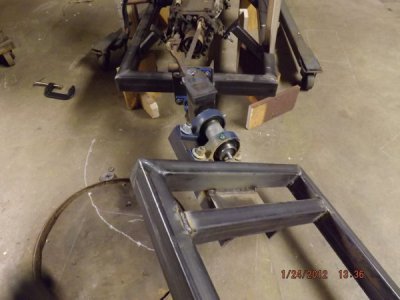
Before starting to build the rear frame, some thought went in to the steering pivot and how it would affect the length of the drive shaft. I had to determine the exact apex of the CV joint when at angle and make sure the apex and steering pivot were both at the same point vertically. If they were different the slip yoke would move too much on the trany output spline and could either bottom out in the trany or come off the spline.
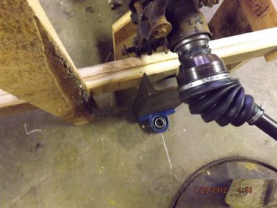
Aligning pivots.JPG

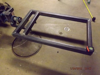
I wanted all the wheels to stay on the ground no matter how uneven the ground was. So in addition to the steering pivot there is a (for lack of a better or proper word) twist pivot. On a log skidder or loader this is done by pivoting one of the axles. Here the whole rear frame is pivoted. In an aircraft this would be called roll.
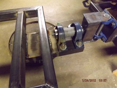
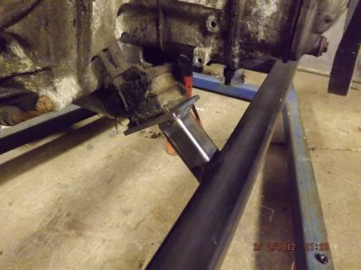
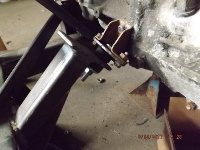
Rear attach detail.JPG

Pivot w twist.JPG

Rear Frame.JPG

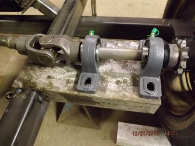
I was planning to build the pivots from scratch and had purchased material to do that but found that at the price these pillow block bearings can be had on EBAY I'd be wasting my time building them.
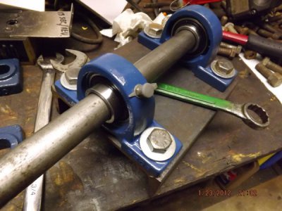
Articulation pivot.JPG


SPINDLES AND DRIVE AXELS

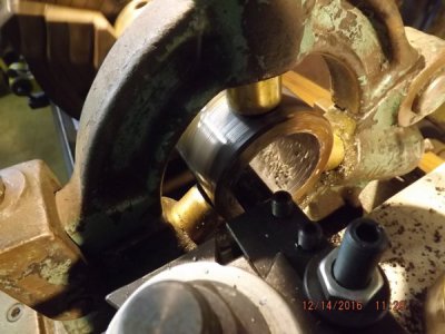
I'm trying to use as much stuff from the car as I can to keep the cost down but one thing that was unusable were the spindles. There's just too many lugs and weird shapes to be able to figure a way to fasten them in place. So I decided to turn new ones on the lathe. I had 2 pieces of heavy wall mechanical tubing, I bought one more and one I turned from a piece of solid stock.
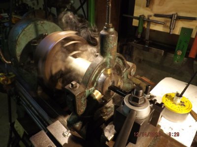
Boring spindle.JPG

Boring spndl 2.JPG

All that boring boring (pun intended) gave me an excuse to make a large boring bar that would gladly take a heavy cut and speed up the operation . See thread on this forum large boring bar

I purchased new sealed ball bearings. The back of the spindle has a welded on shoulder and the bearings are held in by an insert with 3 set screws. Front and rear are built the same but the rear are slightly smaller.
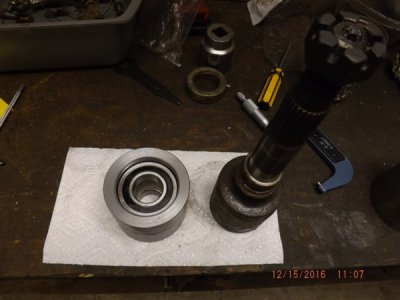
Rear spindle.JPG

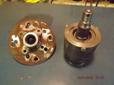
frt spnl rebored hub.JPG

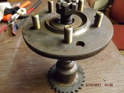
The original wheels and hubs had a 4 hole bolt pattern but the wheels that I wanted to use (from a previous truck I owned with near new grippy tread tires) had 5 hole bolt pattern. So I rebored the hubs on the mill using the DRO bolt circle function. 1/2" fine thread grade 8 bolts were used for studs
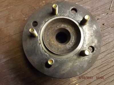
DSCF1794.JPG

DSCF1796.JPG

and they were welded on the back side of hubs.
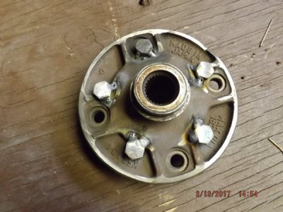
DSCF1793.JPG

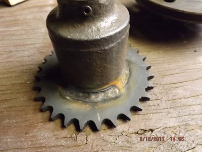
There will be a sprocket and chain reduction at each wheel. I have no need to go fast but must be able to go slow for the snow blower. 11 and 28 tooth sprockets and #50 chain.
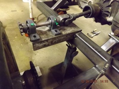
DSCF1752.JPG

DSCF1753.JPG

DSCF1758.JPG

DSCF1795.JPG

These pictures were taken before bracing was added to support members and the plan is for even more.

Thanks for looking
Aaron
DSCF1758.JPG
 
Was it Ford that said to event you need an imagination and a good scrap pile? (very paraphrased I am sure!)

Aaron, it looks like you have both.
Thanks for sharing the build!

-brino
 
MOTOR MOUNTS AND FRAME FLEX ISSUE

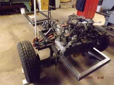
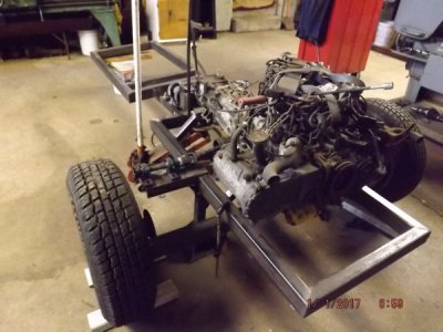
The motor mounts were fabricated from 1-1/2" square tube and sized/designed with the engine blocked on the floor.
DSCF1690.JPG

I had to use some shock absorber grommets to replace the original cushions at the trany that were rotten or torn because most replacement parts for a 32 year old vehicle are not available.
rear mtr mnt.JPG

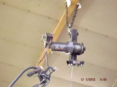
You may notice in many pictures that there are overly long bolts and no lock nuts or washers. This is because the engine and anything else that's removable has yet to be removed so that I can do the finish welding on the underside of the frame and other hard to get at places. This has been done at least twice so far and will probably be done at least 2 more times. The last time I found that I could no longer lift the frames onto a table by hand so a winch was attached in place of where a chain block sometimes hangs from the ceiling so the parts could be lifted onto the table or stood upright on the floor. The winch was far faster than the chain hoist
DSCF1807.JPG

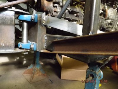
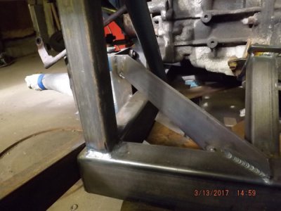
As I was afraid of when I started to choose steel for the frame, (see thread on this forum Steel design ) there is a lot of up/down pressure on the steering pivot which causes the rear member of the front frame to flex (actually twist). This is probably the most highly stressed area of all the frame. It was not noticeable until I clamped a 4 foot piece of bar vertically on it and then loaded some weight in the area. Then it could be measured. The cure was to add bracing from the 2x6" channel that mounts the pillow blocks, tying them to the frame side rails, both sides top and bottom. No more flex seen!
pivot brace.JPG

brace 2.JPG


STEERING AND PEDALS

Much thought went in to choosing and designing the steering. Once the front and rear frames were connected together, a protractor and chalk lines on the floor again gave an idea of how much angle would be needed to make a turn tight enough to turn around in ABOUT a 16' wide roadway. That seemed like a sharp enough turn to go around trees in our swamp if it gets used for skidding. there was also the concern about the rear wheels running into the front wheels on a tight turn but that proved not to be a problem.

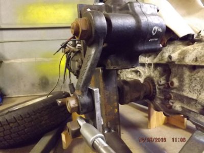
Next was how to make it turn. I knew it could be done with hydraulics but that added a bunch of expense and complexity to it. I wanted to stay away from that if possible. I decided to try a pickup truck steering gear and so that no pump would be needed, I searched for a manual one. They are available on EBAY but I called my local auto salvage and they had a Ford truck manual gear. He said it fit all size trucks (Ranger and full size) for many years. It was even cheaper than EBAY. I think these kind of places are hurting now days because the bulk of their sales is in older body repair parts. Hardly anyone buys used engine and running gear parts anymore. Much unlike when I was fixing cars 20-40 years ago.
Ford gearbox.JPG

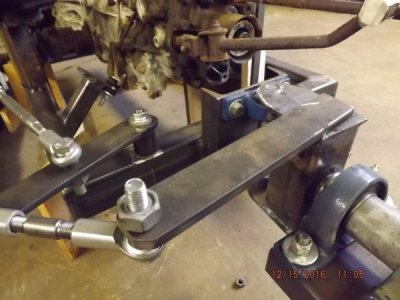
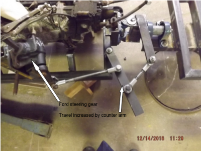
It took a lot of trial and error to get it to turn far enough without hitting some frame part or going too far over travel where the arm would not pull it back to neutral position by itself. The gear did not have enough travel to go all the way both sides so a counter arm to increase the travel distance was necessary.
Linkage.JPG

Steer linkage.png

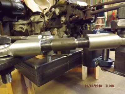
I purchased rod end bearings and turned and threaded links on the lathe.
DIY links.JPG

In order to solve 2 problems at once...

1. lack of power steering

2. making the column shaft and the gear shaft work together (alignment wise)

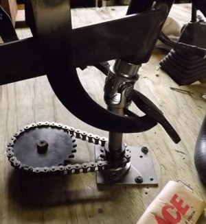
A chain and sprocket reduction was added.
steering reduction.jpg

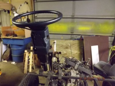
The steering column from the car was shortened and a bushing made for the tube. Then the shaft was turned and a key slot cut in it. (NOTE Anywhere there are u-joints including all the axle shafts they are woodruf keyed with 3/16 x 7/8" woodruf keys). A short shaft was made to go between the u-joint and the sprocket. A flange bearing was added underneath. As it is right now the lock to lock steering wheel travel is 16 turns. If that proves to be awkward the ratio can be easily changed with the sprockets. If it seems too slow a spinner may be all that's needed.

I definitely wanted to use the steering column from the car with all those switches and controls because it would save having to buy. Some switches will be re-purposed.

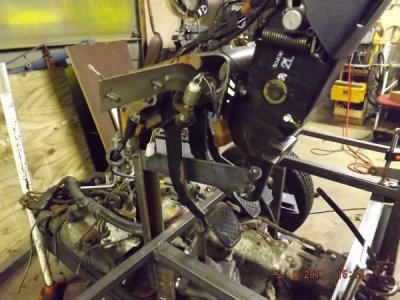
The pedal bracket with all three pedals from the car worked perfectly mounted on a piece of 2" channel and the steering column was fastened to it. The pedals were bent apart to accommodate big booted feet.
DSCF1781.JPG

DSCF1782.JPG

The brake master cylinder from the car will be used and to start with it will be installed less the vacuum assist. That could be added easily if needed.

THE FUTURE

Just a few more posts and you will be caught up to the present time. New stuff will come much slower then!

I also have some trips scheduled for the near future and a knee replacement in May. That will really slow down the project!
Hope you enjoy and maybe get ideas. I also appreciate any suggestions and comments or pics of stuff you have done.

Thanks
Aaron
 
Coming along very Nicely Aaron. Looking forward to future installments, and hope all goes well with the surgery. Cheers Mike
 
multiple post
 
Last edited:
multiple post
 
Last edited:
Much thought went in to choosing and designing the steering.

That is obvious. Very ingenious re-purposing of parts you have going!

How much planning went into the winch electrical connections? :eek:;)
(just kidding, we all do things in a rush sometimes!)

-brino
 
Looks good, I have a dream vehicle for me a tracked power wheelchair . They sell them but not at a price a real disabled person can afford. Or a four wheel drive one to fit a big man not a three ft midget. I've even got several power chairs and scooters to use. The part that worries me is the controller for four wheel drive. Tracks will be easier then 4x4 , I think.
So yes others have fairly large projects. A dozen years ago or so I built a tilting log splitter with old parts and motor . It only had to run at an idle to split the toughest wood, if you sped it up it built to much pressure and would blow the fittings or hoses. Powerfully built the hydraulic pump came from a dump truck. It's still splitting wood to this day same motor and all. Ill be watching for tips on my future builds . Thanks
 
I have a dream vehicle for me a tracked power wheelchair .I've even got several power chairs and scooters to use. The part that worries me is the controller for four wheel drive.

Do you have any plans in your head or elsewhere for this project? Pics of something similar? What kind of terrain would you use it on?

Aaron
 
Do you have any plans in your head or elsewhere for this project? Pics of something similar? What kind of terrain would you use it on?

Aaron
Some would depend on the motor drive I could use. I have two large from a wrangler scooter with low hours on them . And I have a power wheelchair set the same . The scooter is fast which i like . I found some link chain that has angle pieces every few links. Think it's for conveyor belts. Looks about size fifty chain.
I thought about making a frame for the tracks and adapt it to a power chair frame with the scooter motors . But the tracks have me puzzled. I know rollers are needed and drive sprockets . They need to be able to travel in sand and brush . That or make it four whee drive. The scooter drive wheels mount right to the motors if the four of those could work together it would be as good as tracks. I'd need some heavier front end too. I don't know I see them on YouTube and nothing to it for them to make so I figure I can too. But my project list just to get my shop up and running is tops for me now. Going back to the pain doctor next Tuesday see what he says about all the side affects I've been having no fun. If he wants to do another epidural I'm making sure I get a full bottle of saline before I leave, ended up in the er from the last one. They sell them but I'm unable to even think that way. Someday ill do it.
 
Back
Top