-
Welcome back Guest! Did you know you can mentor other members here at H-M? If not, please check out our Relaunch of Hobby Machinist Mentoring Program!
You are using an out of date browser. It may not display this or other websites correctly.
You should upgrade or use an alternative browser.
You should upgrade or use an alternative browser.
Another PM-833TV thread!
- Thread starter M.T. Pockets
- Start date
- Joined
- Jan 11, 2020
- Messages
- 71
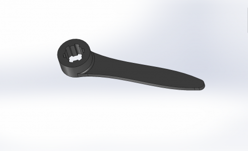
I'm about 5 parts in on this mill and I'm realizing the spindle lock issue people are having. I too kept on having end mills get pulled and drill bits spin in their collets because I couldn't tighten the drawbar enough. I 3D printed this spindle wrench to help tighten the drawbar and it works fairly well. Its just a prototype for now, I'll eventually make one out of aluminum or stainless. Solidworks file attached for anyone that wants to make their own.
FYI, the ID is slightly larger than the 23mm it should be. This is to make room for the hex head of the drawbar.

My other major challenge that I'm going to give some attention to is backlash. Its not terrible, better than other Taiwan made machines I've used **cough** "JET" **cough**, but I still want it better. I'm too cheap for ballscrews so I'll need to find another alternative. I'm able to keep backlash at 2-3 thou on my Taig, maybe I'll look into copying that.
FYI, the ID is slightly larger than the 23mm it should be. This is to make room for the hex head of the drawbar.

My other major challenge that I'm going to give some attention to is backlash. Its not terrible, better than other Taiwan made machines I've used **cough** "JET" **cough**, but I still want it better. I'm too cheap for ballscrews so I'll need to find another alternative. I'm able to keep backlash at 2-3 thou on my Taig, maybe I'll look into copying that.
Attachments
- Joined
- Jan 11, 2020
- Messages
- 71
My mill doesn't have a low range, its got the belt and pulleys. So far yes, its been strong enough. I made it out of some PLA I had laying around and used some thick walls and 25% infill on the print. I don't expect it to last forever, just to prove that the geometry works.
- Joined
- Oct 27, 2016
- Messages
- 286
MT Pockets, nice work on getting your new mill setup and the DRO install looks good.
I noticed that you have the red shipping spacers still installed between the read head and the scale in your photos, did you remove them or leave them in?
Also why is backlash an issue now that you have a DRO installed?
David.
I noticed that you have the red shipping spacers still installed between the read head and the scale in your photos, did you remove them or leave them in?
Also why is backlash an issue now that you have a DRO installed?
David.
- Joined
- Jan 11, 2020
- Messages
- 71
Thanks Kiwi, I left the spacers in as the manufacture describes them as "wipers". Didn't think it would hurt to leave them on.
The backlash isn't an issue with the DRO, its always been an issue, mainly because I want to do climb milling without breaking stuff. I haven't messed with the leadscrew nuts yet so that will be step one.
The backlash isn't an issue with the DRO, its always been an issue, mainly because I want to do climb milling without breaking stuff. I haven't messed with the leadscrew nuts yet so that will be step one.
Last edited:
- Joined
- Jun 12, 2014
- Messages
- 4,806
I do climb cutting quite a bit, never seemed to be an issue to have a few thousandth of play which is pretty much the norm even for a new machine. Ball screws can get away from you with climb cutting, ok for CNC but not so much for manual. Also a function of your gibs. Nice build on the stand/install.
- Joined
- Jan 11, 2020
- Messages
- 71
Thanks mksj. For the backlash, we're not talking a few thou here, were talking about 10-15 thou in the x and y. Way more than there should be and I've had a 1/2 end mill already grab a few times. I'd like to get it down to a few thou like I have on my Taig which I think is doable, just needs some tuning. I agree about the ballscrews, I don't want them on a manual machine. Worst case is I buy pre-loaded lead screw nuts but that probably wont be necessary.
- Joined
- Jan 11, 2020
- Messages
- 71
It took a few hours but I got the backlash fixed, or at least better. I was originally measuring about 10 thou on the x axis and about 15 on y. After a lot of measuring and fiddling I found it was due to a combination of preload on the lead screw bearings and backlash in the brass split nuts.
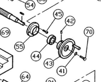
As shown in the picture below, the preload on the bearings comes from the #70 screw, there's no separate nut for it. After torquing the x and y handle screws to about 15 ft-lbs, using my calibrated arm, the backlash from the bearings came down to about 0.5 thou. I also noticed that these don't appear to be angular contact bearings, just regular radial bearings. After adding the preload the bearings feel a bit gritty and I don't think they will last all that long. If/when they do fail I'll try to replace them with some angular contact bearings.

The other large source of backlash was the split nuts. They both needed to be tightened a pretty good amount. I didn't need to tighten them all the way but they're not that far from it. They're made from casted brass (which isn't a bad thing, these are cheaper to replace than lead screws) so not sure how long they will last before needing to be tightened again. These will probably eventually get replaced too.
After making all the adjustments I'm down to about 2-3 thou for both the x and y and the table feels a lot less loosy goosy, although a bit gritty because these radial bearings aren't meant for axial load. I'm going to cut some mild steel on it this weekend and we'll see how she handles climb milling now.
As shown in the picture below, the preload on the bearings comes from the #70 screw, there's no separate nut for it. After torquing the x and y handle screws to about 15 ft-lbs, using my calibrated arm, the backlash from the bearings came down to about 0.5 thou. I also noticed that these don't appear to be angular contact bearings, just regular radial bearings. After adding the preload the bearings feel a bit gritty and I don't think they will last all that long. If/when they do fail I'll try to replace them with some angular contact bearings.

The other large source of backlash was the split nuts. They both needed to be tightened a pretty good amount. I didn't need to tighten them all the way but they're not that far from it. They're made from casted brass (which isn't a bad thing, these are cheaper to replace than lead screws) so not sure how long they will last before needing to be tightened again. These will probably eventually get replaced too.
After making all the adjustments I'm down to about 2-3 thou for both the x and y and the table feels a lot less loosy goosy, although a bit gritty because these radial bearings aren't meant for axial load. I'm going to cut some mild steel on it this weekend and we'll see how she handles climb milling now.

