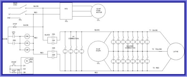
The idler is a standard 9 lead, Y connected.
http://www.baldor.com/catalog/CEM2333T#tab="specs"
The lathe 1 hp hydraulic pump is also a 9 lead, Y connected, but the other motors are all AC servos.
The following analysis may help your efforts to validate the design and if you are getting the targeted performance of your system. Double check my math, but it seems viable.
On the 15 hp Baldor - since you are running 2 Y (low voltage)or two identical Y windings in parallel, the impedance of the windings would be half than if you ran it in the 1 Y configuration. The 0.83 power factor rating for the motor does not indicate if that is for the motor running 1Y or 2Y, but my expectation is that the winding configuration would impact power factor. This is where having the actual measured impedance of the motor windings would have been more valuable – and especially when we are configuring this 15hp motor to be placed in parallel with yet another (load) motor winding system. But let's go with the manufacturer’s .83 rating for now:
Looking at the 15 hp motor alone and to take the pf from 0.83 to 0.95
AT.83 PF
Watt(P) (input) to motor = HP x 746 / eff. = 12.11 kW (bottom of the pftriangle)
VA(S) =P/pf = 14.6 kVA
VAR(Q) = VA Sin Θ= 14.6 kVA Sin 33.9 degrees = 8.14 kVAR
I= VA/V = (14.6 kVA/(230 x 1.73)) = ~36.7 A
AT.95 PF
Watt(P) (input) to motor = HP x 746 / eff. = 12.11 kW (bottom of the pftriangle)
VA(S) =P/pf = 12.7 kVA
VAR(Q) = VA Sin Θ= 12.7kVA Sin 18.2degrees = 3.97 kVAR
I= VA/V = (12.7 kVA/(230 x 1.73)) = ~32A
So 8.14 - 3.97 kVAR = 4.17 kVAR leading are needed or C=kVAR/ώ
V2=4.17 kVAR/2*Π*f*V2=209mfd. Connecting the capacitors in DELTA across the 2Y connections =209 mfd/3 = 70 mfd across each line.
So this approach improves the power factor for the 15 horse motor from0.83 to 0.95 and reduces the current from 36.7 A to 32 A.
Looking at the 1 hp motor alone and using typical NEMA values for eff. = 82.5% and pf = 0.8:
AT.80 PF
Watt(P) (input) to motor = HP x 746 / eff. = 0.9 kW (bottom of the pftriangle)
VA(S) =P/pf = 1.13 kVA
VAR(Q) = VA Sin Θ= 1.13kVA Sin 36.9degrees = 0.678 kVAR
I= VA/V = (1.13 kVA/(230 x 1.73)) = ~2.8 A
AT.95 PF
Watt(P) (input) to motor = HP x 746 / eff. = 0.9 kW (bottom of the pftriangle)
VA(S) =P/pf = 0.95 kVA
VAR(Q) = VA Sin Θ= 0.95kVA Sin 18.2degrees = 0.297 kVAR
I= VA/V = (0.95 kVA/(230 x 1.73)) = ~2.4 A
So 0.678 – 0.297 kVAR = 0.381kVAR leading are needed or C=kVAR/ώ
V2=0.381 kVAR/2*Π*f*V2=19mfd. Connecting the capacitors in DELTA across the Y connection = 19mfd/3 = 6.3mfd across each line.
So this approach improves the power factor for the 1 horse motor from0.82to 0.95 and reduces the current from 2.8A to 2.4A
Therefore, with the 15 hp generator motor in parallel with the 1 hp load motor, the total capacitance across-the-lines would, in theory, be 70 + 6.3mfd = ~75 mfd to bring the system pf to 0.95 and the total corrected rms current you should see on your Fluke should be about 34.5 A.
What is missing in the analysis is the fact that the 15 hp drive motor is being driven with one broken leg, so its shaft hp would be reduced at least one third and the inrush power requirements will increase correspondingly, and its anybody's guess how the power factor will present until the motor comes to steady-state speed.
However, the analysis is valid if the drive motor was operated in a true motor-generator configuration.


