Another switch wiring question

Cdsloop

Registered
Registered
Joined
Jan 25, 2021
Messages
7
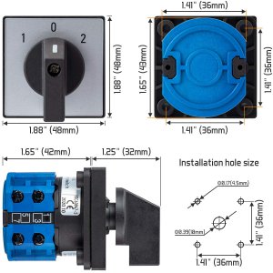
I was recently given a Jet 1024 that is in rather poor shape, but I am working to get it operational order. I have verified that the single phase 120v induction motor will run in both rotations according to the wiring diagram on the motor tag. When I got it, it was wired to a cam/toggle switch on the face in the CCW direction only. I have no idea if the switch on the machine was original, but I suspect that it was not. I want to re-wire it to use a cam or toggle type switch in the factory location similar to the switch in the attached photos. Can someone help me with a switch recommendation that I might get through Amazon to accomplish forward and reverse motor rotation through a single switch? I'll also need assistance to get the recommended switch wired to my machine. Thank you for your help!motor tag.jpgswitch face.jpgswitch rear.jpgswitch side.jpg
 
First observation is that a motor of that size should be run on 230 volts since 15 amps is the limit for most residential outlets. It may run on a standard outlet without any load but will trip the breaker when you start loading it.
Second is that it might be difficult to find a multi-pole switch that would fit in the existing mounting hole- most of the affordable high current import rotary switches have a four bolt faceplate style of mounting that I have seen
I can post some possible switch choices for you from Amazon if you want and help you wire it up but you really should plan on 220/240 volts power
-Mark
ps some folks have 120 volt 20 amp outlets in their garages, you'll have to check your situation
 
Last edited:
First observation is that a motor of that size should be run on 230 volts since 15 amps is the limit for most residential outlets. It may run on a standard outlet without any load but will trip the breaker when you start loading it.
Second is that it might be difficult to find a multi-pole switch that would fit in the existing mounting hole- most of the affordable high current import rotary switches have a four bolt faceplate style of mounting that I have seen
I can post some possible switch choices for you from Amazon if you want and help you wire it up but you really should plan on 220/240 volts power
-Mark
ps some folks have 120 volt 20 amp outlets in their garages, you'll have to check your situation
I'm not opposed to changing it over to 240v since that will give me a more usable machine. I have 240 in my barn where the lathe will be used, so that isn't a problem. I'll probably run another dedicated circuit for the lathe anyway so I don't have to unplug my compressor all the time. I would prefer to use a switch similar to the one pictured if I can. I am capable of wiring in a drum switch, but would prefer to keep the factory type of switch to keep things clean and uncluttered.
 

Attachments

  • 71GB6VibBdL._SL1200_.jpg
    71GB6VibBdL._SL1200_.jpg
    164.3 KB · Views: 21
If you can find a switch that fits and has at least 3 poles post it here before you order it, I'll let you know if it's suitable
It should be rated at least 20 amps at 600 volts
-Mark
 
I just ordered that switch and the enclosure Amazon offers to mount it in, if I can't use it in the original switch location on the machine. I'll need some assistance in wiring it when it arrives! Thanks for the help so far.
 
I'll do a sketch for you, stay tuned
Here you go: add switch jumpers and connect as per sketch
Be sure to add a ground wire to the motor (not shown)
If switch handle position opposite from desired, swap motor wires 1 and 4
 

Attachments

  • bao1.jpeg
    bao1.jpeg
    35.3 KB · Views: 22
Last edited:
I'll do a sketch for you, stay tuned
Here you go: add switch jumpers and connect as per sketch
Be sure to add a ground wire to the motor (not shown)
If switch handle position opposite from desired, swap motor wires 1 and 4
Forgive my ignorance, but I just want to make sure that I understand this correctly, as this is my first rodeo in wiring something this detailed. Per your sketch, I need to bring one leg of the 240 in on position 1 of the switch, and add a jumper from position 1 to 3. I bring the other leg of 240 in on position 9 and add a jumper from position 9 to 11. I will jumper connect positions 2,4, and 5 together, and take one of those to wire 1 of the motor. I will jumper positions 6 and 8 together and take one of those to wire 6 of the motor, and jumper positions 7, 10 and 12 together and take one of those to wire 4 of the motor. I will connect motor wires 2,3,and 5 together at the motor. Make sure motor is grounded. Is this correct? Thank you so much for your assistance!!
 
Yes to all. All groups of numbers mean those are jumpered together.
Check your connections carefully.
Be safe
-M
 
Here is an alternate version which would improve the lifetime of the switch contacts slightly:
Both versions will work but this one would be the best from an engineering standpoint
 

Attachments

  • bao2.jpeg
    bao2.jpeg
    35.1 KB · Views: 9
Back
Top