Another Tool & Cutter Grinder

It took quite a while, but I have learned that lesson to the point that when critical in required, I do it. When it's not, I do 'good enough' and move on. I have found that following this simple rule has greatly increased my 'fun factor' in my shop. :)
 
And then the next question thought of by the new guy, "Just who sets the ball?" Extremely simple question to answer, YOU DO. Every time you get better you reset the Ball.

"Billy G"
 
Mark
I was thinking about the grinder while I was in the shop and looked at a Morse taper and came up with the idea of the tang. Put a tang on the grinder wheel shaft that would only go one way and the same to the ER holder. That way you can put the stone back into the head as close as possible without all the extra work. Just and idea
Nelson Collar
 
wrmiller, Yes I am trying to get to that point, in fact, I have been trying to get to that point for over forty years :grin:

I never thought of that Bill Gruby, but you are right. Every time I master something I set the bar a little higher.

Nelson, the only problem is the shaft has to be kept as short as possible. The shorter , the easier to control flex and runout.


I find the details are taking more time than the actual machine build. But I think it works that way with every thing.
I painted the screw support bar on the column and it looks much better.
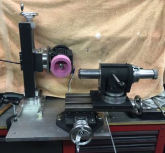
grinder1.jpg
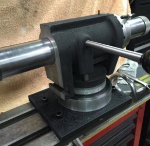
I also got the air bearing mounted. It was designed to be on a table with a center slot. It is held in place by a 1/2-13 bolt down through the center and had 10 mm dowel pins 180 degrees apart on the bottom. My table does not have a center slot so I made an adapter plate from 1/2" thick aluminum ( the air bearing body and base are cast aluminum). I drilled holes in the plate to match the bottom of the bearing base as close as possible ( this was difficult as it had to be as exact as possible).
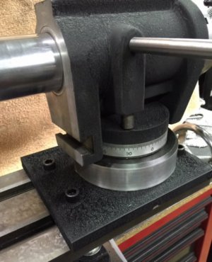
air bearing1.jpg
I then drilled and reamed the dowel holes to .500 and inserted the dowels. I must have done good because the bolt hole is reamed at .500 and the bolt went right in.:grin: I drilled four .375 holes for the bolts to go in the four T nuts that anchor the assembly to the table. AND NO, there is no paint on the plate under the bearing. ( I masked that area off :grin: ).
air bearing2.jpg
grinder1.jpg This is how the grinder is shaping up so far. I'm not putting down the Bonelle, it is a fine machine and works well, but this grinder will have half the hours building and is much more superior in my opinion.

I am waiting for the control box for the electrics. It is coming from China ..... some day...
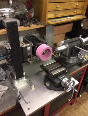
The column and grinding head on this machine just blows me away. it is massive, very solid and works very well. I am very impressed with this design. I hope it grinds as well. I am starting to work on the fixtures while waiting for parts. I will be making a three jointed articulating vise fixture, a spindle and tool height gage, and a work head for the ends of end mills.

Keep watching.....more to come. column 4.jpg
 
Pretty impressive Mark. I'm really liking this design. :)
Yes, if you build a grinder, I think this should be the one. Much of it is patterned similar to a commercial one that sells for $10,000 without the extras. I selected features from three different brands that I wanted and rolled them into one machine. I even went back and studied Bill Gruby's build for some inspiration of some features.And I am making a few changes during the build when I find or think of something better. I am open to suggestions as where to put the electrics control box. I have been leaning towards the rear right corner, but just not sure yet. Any suggestions?
 
Yes, if you build a grinder, I think this should be the one. Much of it is patterned similar to a commercial one that sells for $10,000 without the extras. I selected features from three different brands that I wanted and rolled them into one machine. I even went back and studied Bill Gruby's build for some inspiration of some features.And I am making a few changes during the build when I find or think of something better. I am open to suggestions as where to put the electrics control box. I have been leaning towards the rear right corner, but just not sure yet. Any suggestions?

Can't tell from the pics, but is there enough room back right to put a small vertical arm and mount for the box to keep it up and away from any flying grit?
 
one of the fixtures needed on a tool and cutter grinder is an articulated vise fixture. they usually have two or as many as three rotating joints and a small vise or collet fixture can be fastened to it to present tools and small parts to the grinder at a desired angle. they can be bought , but even used ones can run $200 to $300.........sooooo ...in my usual thrifty way, I will make one.
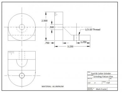
Grinding Fixture Vise.jpg This is the print I designed to make the joints. I will need two of these. I start with a 2 1/2" X 3" X 3 1/4" aluminum block.
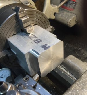
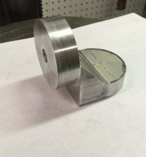
turning block.jpg It is chucked in the lathe and the end turned to 2 1/2" round. ( there is a step on one side. I milled that first to make the lathe work easier). At this point, I also engraved the 360 marks around the turned portion.

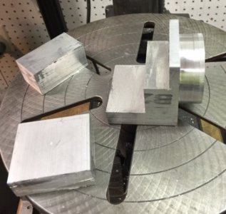
rough cut block.jpg I put the piece in my band saw and cut the excess out in two pieces. This left me two nice pieces of aluminum that can be used later for something instead of making chips of it.
Now , off to the milling machine.

After a couple hours of milling, I have the basic shape.
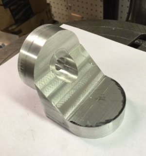
milled block.jpg The 1/2" reamed hole was put in while in the lathe so it would be perfectly centered and concentric. The radius end was rough milled and finished on my belt sander. With a little practice, you can do a radius this way so good, it can be as good as if done with a rotary table and mill. ( but a lot easier and faster). I next need to drill the hole in this end which will be tapped at 1/2-20 threads.
milled block2.jpg Another view.
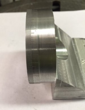
milled block3.jpg This photo shows the fine lines for the degree markings. I tried stamping numbers but there is not enough room for them and they were very hard to keep in line so I turned them off. I will put a "zero" on and leave the rest blank. usually it will stay where it is set or move very little. I will search for another way to number these. I will be painting these with black wrinkle finish ... I think.

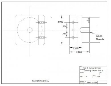
Grinding Fixture Vise 2.jpg This is the print for the small vise that will go with this fixture. It will be made from a piece of steel or cast iron. not sure which yet.
 
Someone ask me why I made this fixture from aluminum. The answer is ..... Because it is easy to work with and this is a grinding fixture. You ain't supposed to be beating it with a hammer or using a prybar on it. It's purpose is only to hold tools for grinding. The small vise for it will be steel because it needs to be stronger. The aluminum joint pieces are .750 thick, so they are pretty stout. There are no big forces grinding tools. I was going to use steel so I could also use it on my mill but had the aluminum. So.... I will just dedicate it to the grinder. ( I personally don't think these should be used on a mill even if they are cast iron as many were).
 
Back
Top