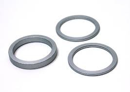
Appropriate steel for a spacer?

I agree the stackup on the shaft makes no sense.
The 2 dogs are not meshing with anything - and the spacer looks like it would fit over one of the dogs. Just hard to tell how it is assembled from the pictures.
It looks like the crack is from compression not torsion. Like something was assembled wrong and tightend down.
 
I agree with the use "steel" crowd, especially if it is hard (file test would tell that story). If it works like we think, the spacer is compression loaded. As suggested by francist, using shims may be a better path. In general, cast housings don't crack in general use. Something moved that wasn't supposed to (wear), something stopped fast (crash), or things got loaded heavy for awhile. What does the bottom of the hole this sits in look like? As a group, we often buy used equipment we don't know the history of, or who or how good the last guy was that messed with it. Not likely Delta/Rockwell missed it by 0.065. It is a helical gear, so shaft/spacer could see some thrust load. You said it runs in oil, what happens if the oil isn't there? Who rubs on who (maybe for 65 thou)? You are looking at parts we can't see.. But no one who gets into this hobby/interest/obsession is a mechanical idiot - noob or otherwise, you already tore into something way deeper than most would. Good luck with the quest.
 
If you have a register where this spacer pushes against, your best bet is to make couple of spacer shims so you can allow some endplay so it want seized and is probably what is missing, manufacturers often use them to set the endplay and allow for future adjusting as the machine is being used.
download (1).jpg
 
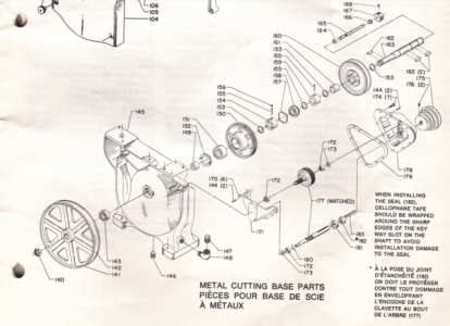
Thanks everyone for the advice, here's a diagram of the assembly from the instruction guide on Vintage Machinery:
Stackup.png
What makes sense to me is for nut (#140) to tighten the wheel (#141), the inner race of the bearing (#143), the spacer (#149), the inner race of the large gear wheel's bearing (#151) against the retaining ring (#153).
Since the big gear wheel rides on a bearing, I don't see why you'd need axial play there (but I'm willing to learn).
As-is, when nut (#140) is tightened, it'll pull the opposite side's bearing (#158) into the casting and crush it. Note that this casting is hollow, with fairly thin walls (1/8" maybe), which is different from the woodcutting model, where I believe the spindle goes through a bore solid through the casting.
I also don't think it makes sense for the big gear wheel (#150) to rub against the casting at one end of the axial play.

Note that there's a double clutch on the shaft to switch between direct drive for wood cutting through pulley (#160), to metal cutting through the gearbox and the big gear wheel (#150). When disengaged, the pulley will idle on a bushing (#161 - which I'll have to replace, oilite ordered), and when engaged, the gear wheel will idle on the bearing (#150).

EDIT: I was typing while you were posting your pics. It looks as though your spacer has a shoulder, or am I seeing it wrong? Is the spacer
located between the two bearings? It's not completely clear how the assembly goes together. But, again, if the spacer is simply located
between the bearings and rotates with the inner races on the shaft, the material probably isn't critical. Or, is there more going on here?

Yes, the spacer is steel, and it's located between two bearings. There's a shoulder on the shaft, as the IDs of the two bearings are different, and so there's a step in the spacer bore.

The big gear has helical teeth and such a gear will always place an axial thrust on the shaft it spins on. Are you absolutely certain that the cracked housing is because of the deformed or altered spacer you intend to make? Is it possible the axial forces are excessive for some reason? Are you certain this was assembled properly? Maybe something is in there backward...
Yeah, I don't know the history of this bandsaw, except that it's led a hard life. It was covered in chips-in-cutting-oil and sawdust when I got it, the bottom of the base was quite rusty, the big pulley was quite corroded and the keys in the step pulleys were out of place - one of them pushed all the way up the shallow of the keyway and nearly rubbing on the casting.
One thought I had was that the bearing was installed inside-out. This bearing has an inner race that's wider than the outer race, and offset to one side - by just about 65 thou.
I don't think this makes sense however, as the shielding on this bearing gives it an orientation for "outside", plus there'd have to be a spacer on the outside of the bearing to locate the wheel correctly...
 
Last edited:
Depending on the diameter, you may be able to source existing valve spring shims to accomplish what you need. Pretty much everything that turns is going to require some end play, 3-5 thou should do it. Agree that brazing up the crack is the right way to go, but even if you stick with the JB solution, I would drill out both ends of the crack to keep it from spreading. Mike
 
The diagram shows 2 parts (149 & 152) between the bearing in the housing (143) and the bearing that supports the large gear (151). You have one.
The parts list
shows 149 as a spacer and 152 as a retainer nut which appears to secure the bearing (151) into the gear. Is that retainer installed in the gear?
If it's missing, then you may have a shop made part fabricated to replace 149 and 152. The other option is that someone lost the spacer along
the way and made a replacement, but dimensioned it wrong.
 
One thought I had was that the bearing was installed inside-out. This bearing has an inner race that's wider than the outer race, and offset to one side - by just about 65 thou.

To which side was it offset?
 
The diagram shows 2 parts (149 & 152) between the bearing in the housing (143) and the bearing that supports the large gear (151). You have one.
The parts list
shows 149 as a spacer and 152 as a retainer nut which appears to secure the bearing (151) into the gear. Is that retainer installed in the gear?
Thanks, the retaining nut is in place on the gear. It rotates with the gear and the outer race of the bearing, while the spacer slips through it and rotates with the shaft, so I think that's all working as intended :).

The other option is that someone lost the spacer along
the way and made a replacement, but dimensioned it wrong.
Yeah - that's another possibility.

To which side was it offset?

It was offset to the outside, which I think is the orientation it's designed for, as that provides spacing for the cast aluminum wheel away from the bearing shield and the outer race. Also the bearing has the shielding on the side where the inner race protrudes, which is consistent with "outside".
 
Interesting, by my measurements the spacer would be 3/4" on the dot to pick up the play on the shaft. Surely that's not a coinkidink?
 
It sounds as though you've figured out what you need. A steel spacer made from whatever you have on hand sounds
like it would solve your problem.
 
Back
Top