- Joined
- Sep 22, 2010
- Messages
- 7,223
New Taig Lathe Kit Assembly
This four page article shows the various stages and techniques in assembling the Taig Lathe Kit K1019
Page 2 of 4, Go to page 1, page 3, page 4
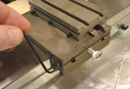
Slide the carriage on and loosen the gib adjustemnt lock screws.
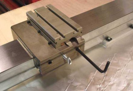
Tighten the screws evenly so that it slides but has no play.
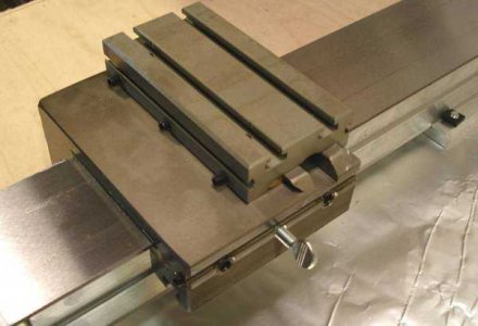
The thumbscrew should lock the carriage when tightened, but allow it to slide when loose.
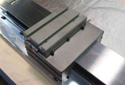
On to the cross slide.
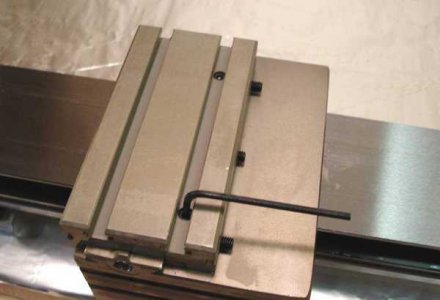
Loosen the gib locking screws.
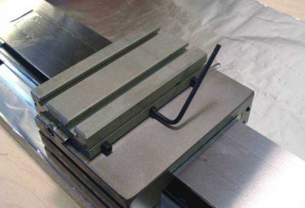
Loosen the gib screws.
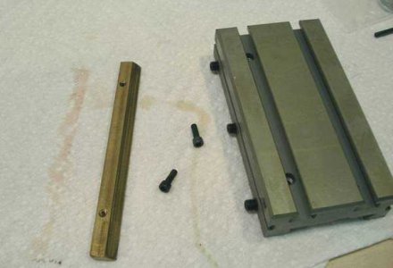
Slide the slide off and remove the gib.
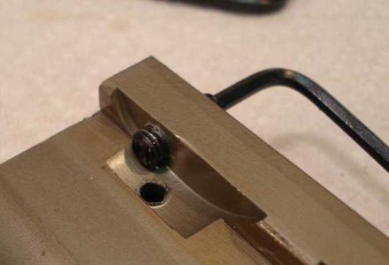
Screw the screws in - this will remove any burrs left in the hole.
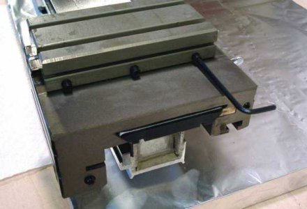
Adjust the gib screws. The gib locking screws should be slack.
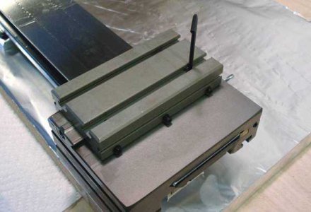
Snug up the gib locking screws, this may take several iterations as this usually tightens things up a bit, and then you have to adjust the gibs again.
Page 2 of 4, Go to page 1, page 3, page 4
Back to the Taig Lathe Page
New Taig Lathe Kit Assembly
This four page article shows the various stages and techniques in assembling the Taig Lathe Kit K1019
Page 3 of 4, Go to page 1, page 2, page 4
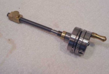
The cross slide screw assembly. Unscrew the lead screw nut (left hand).
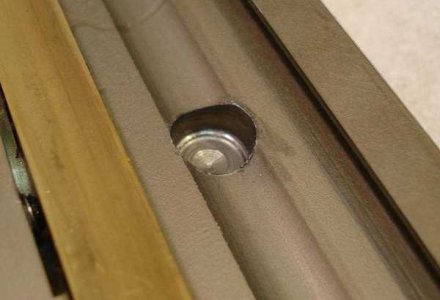
There is usually a burr in the hole and the nut post may be a bit tight, some creative deburring will make assembly easier.
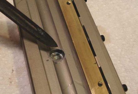
Deburred.
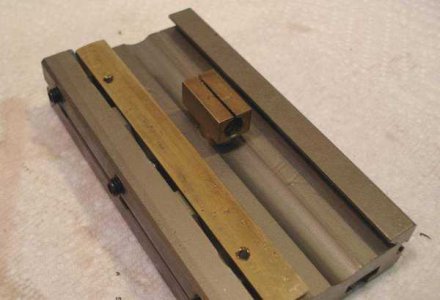
The mounting hole and the nut, you want the long end facing away from the front of the lathe.
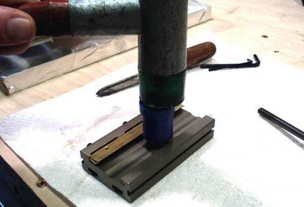
Tapped in with a mallet.
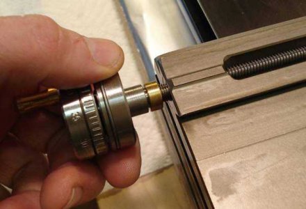
Screw in the cross slide screw assembly.
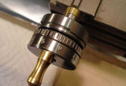
That ring provides a zero mark.
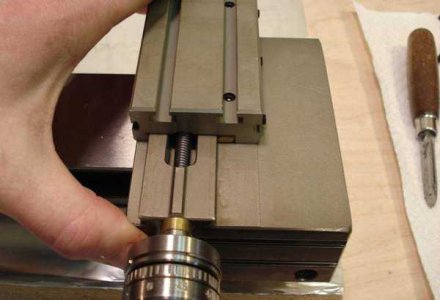
Screw the cross slide on.
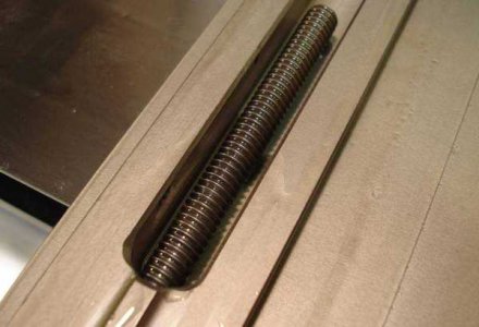
Oil everything with either 20 or 30 wt oil or better yet, way oil.
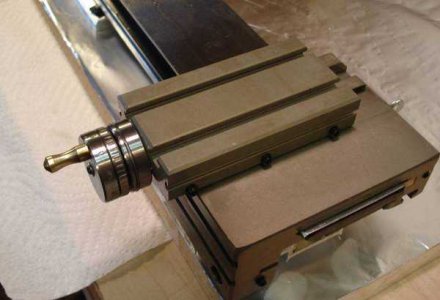
Test for smooth travel. Adjust gibs, tweak the nut alignment, etc to make smooth.
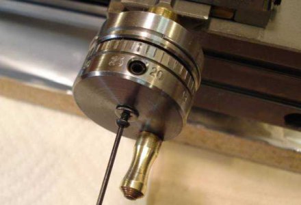
These steps aren't needed, but here just in case you need to adjust the dial. Remove dial lock screw.
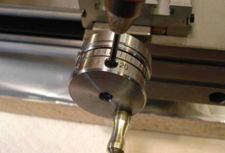
Dial setscrew.
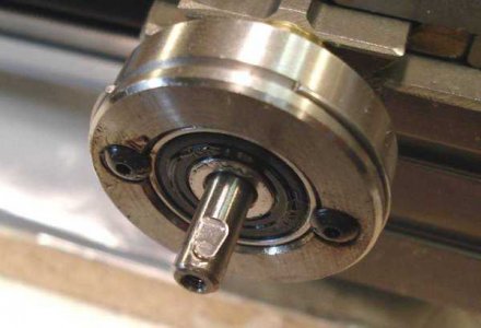
Leadscrew end. The flat is for the dial setscrew to bear against.
Page 3 of 4, Go to page 1, page 2, page 4
Back to the Taig Lathe Page
New Taig Lathe Kit Assembly
This four page article shows the various stages and techniques in assembling the Taig Lathe Kit K1019
Page 4 of 4, Go to page 1, page 2, page 3
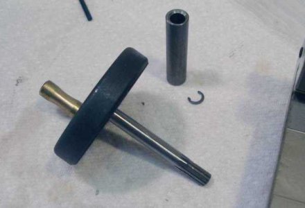
Carriage pinion, eccentric, etc.
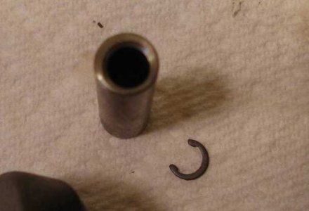
The eccentric.
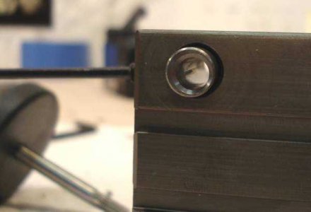
Insert the eccentric bushing in the carriage. Make sure the thick side is against the locking screw.
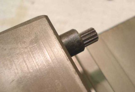
The pinion sticks out the bushing.
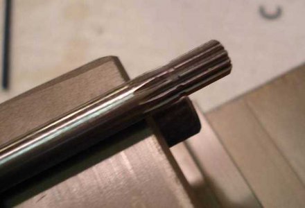
For some reason the groove that was used for the c-clip doesn't extend past the bushing anymore. I think they have a ton of the pinions with this old feature.
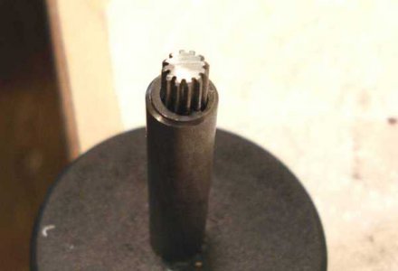
The c-clip slides on (it takes a while to line it up and get it on, be patient...) but doesn't hit the groove. I usually leave the c-clip off anyway as it makes cleaning easier.
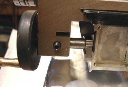
How everything should look.
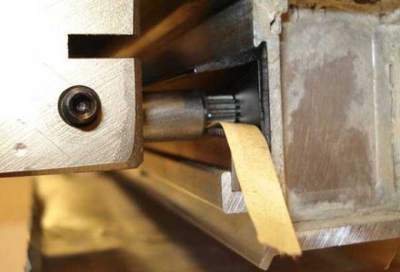
Adjust the eccentric so that the pinion grabs a piece of paper between it and the rack.
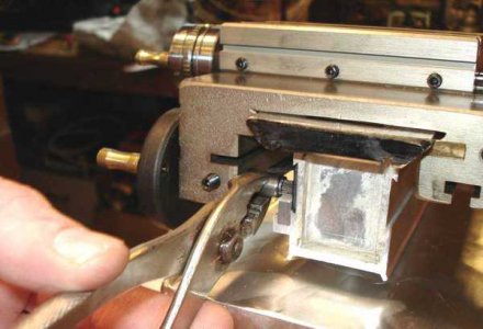
I used pliers, gently(!)
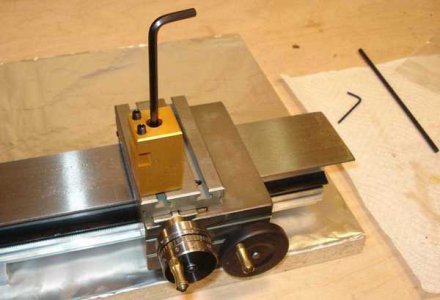
That's how the toolpost mounts...
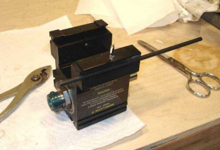
Depth stop in place on the headstock.
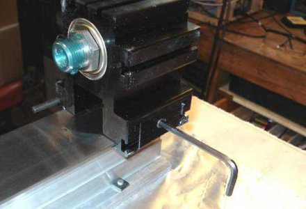
One screw through the clamping shoe locks the headstock in place.
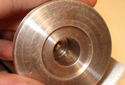
You may need to debur the inside of the headstock pulley where the setscrew comes through.
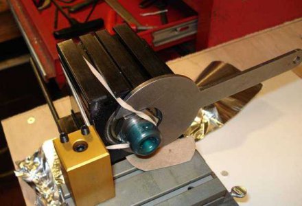
One way to immobilize the spindle.
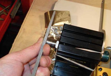
So I can file a flat on the headstock shaft. Not mandatory but it makes it easier to remove the pulley later.
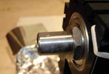
Flat.
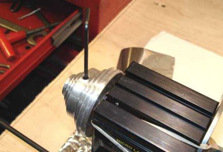
Tightening the pulley setscrew. That's it!
Page 4 of 4, Go to page 1, page 2, page 3
Back to the Taig Lathe Page
This four page article shows the various stages and techniques in assembling the Taig Lathe Kit K1019
Page 2 of 4, Go to page 1, page 3, page 4

Slide the carriage on and loosen the gib adjustemnt lock screws.

Tighten the screws evenly so that it slides but has no play.

The thumbscrew should lock the carriage when tightened, but allow it to slide when loose.

On to the cross slide.

Loosen the gib locking screws.

Loosen the gib screws.

Slide the slide off and remove the gib.

Screw the screws in - this will remove any burrs left in the hole.

Adjust the gib screws. The gib locking screws should be slack.

Snug up the gib locking screws, this may take several iterations as this usually tightens things up a bit, and then you have to adjust the gibs again.
Page 2 of 4, Go to page 1, page 3, page 4
Back to the Taig Lathe Page
New Taig Lathe Kit Assembly
This four page article shows the various stages and techniques in assembling the Taig Lathe Kit K1019
Page 3 of 4, Go to page 1, page 2, page 4

The cross slide screw assembly. Unscrew the lead screw nut (left hand).

There is usually a burr in the hole and the nut post may be a bit tight, some creative deburring will make assembly easier.

Deburred.

The mounting hole and the nut, you want the long end facing away from the front of the lathe.

Tapped in with a mallet.

Screw in the cross slide screw assembly.

That ring provides a zero mark.

Screw the cross slide on.

Oil everything with either 20 or 30 wt oil or better yet, way oil.

Test for smooth travel. Adjust gibs, tweak the nut alignment, etc to make smooth.

These steps aren't needed, but here just in case you need to adjust the dial. Remove dial lock screw.

Dial setscrew.

Leadscrew end. The flat is for the dial setscrew to bear against.
Page 3 of 4, Go to page 1, page 2, page 4
Back to the Taig Lathe Page
New Taig Lathe Kit Assembly
This four page article shows the various stages and techniques in assembling the Taig Lathe Kit K1019
Page 4 of 4, Go to page 1, page 2, page 3

Carriage pinion, eccentric, etc.

The eccentric.

Insert the eccentric bushing in the carriage. Make sure the thick side is against the locking screw.

The pinion sticks out the bushing.

For some reason the groove that was used for the c-clip doesn't extend past the bushing anymore. I think they have a ton of the pinions with this old feature.

The c-clip slides on (it takes a while to line it up and get it on, be patient...) but doesn't hit the groove. I usually leave the c-clip off anyway as it makes cleaning easier.

How everything should look.

Adjust the eccentric so that the pinion grabs a piece of paper between it and the rack.

I used pliers, gently(!)

That's how the toolpost mounts...

Depth stop in place on the headstock.

One screw through the clamping shoe locks the headstock in place.

You may need to debur the inside of the headstock pulley where the setscrew comes through.

One way to immobilize the spindle.

So I can file a flat on the headstock shaft. Not mandatory but it makes it easier to remove the pulley later.

Flat.

Tightening the pulley setscrew. That's it!
Page 4 of 4, Go to page 1, page 2, page 3
Back to the Taig Lathe Page
Last edited by a moderator:

