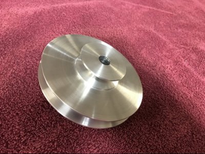
Atlas 9-428 Motor Pulley

JPMacG

Active User
H-M Supporter - Silver Member
Joined
Mar 22, 2014
Messages
847
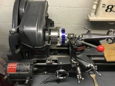
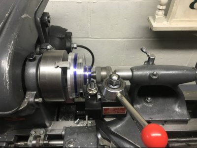
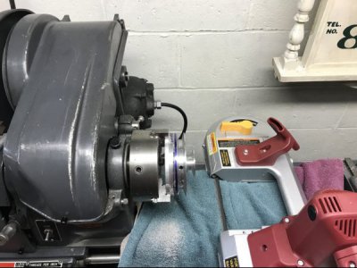
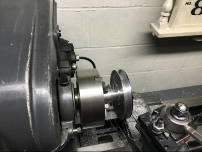
I finally found the ambition, spare time, and confidence to try making a replacement pulley for my lathe. The original was missing and I had been using a small single-step cast pulley until now. It went well - not as difficult as I had imagined. The material is 6061T6 from Stoner Metals. I now need to make another for the MFC.

IMG_1547.JPGIMG_1491.JPGIMG_1498.JPGIMG_1538.JPGIMG_1544.JPG
 
Hi, I know this post is kind of old, but I need to make one of these for my 1936 Craftsman and I never had the original motor pulley, can you let me know what the nominal pulley ODs are? I can't seem to find them anywhere in old Atlas or Craftsman catalogs. Thanks!
 
I can do better than that. We don't have the original pulley drawings because the pulleys are still supplied by Clausing. But in Downloads in the A-C lathe drawings folder is a reverse-engineered drawing for the 10-428. The only difference between the two is the motor shaft bore and maybe the 9-428 didn't have a keyway (I can't recall whether the 48 frame motor had a keyway or a flat). At least two pulleys have been made from the drawing, which was done by a member over on atlas-craftsman@groups.io. I know that the factory dropped the 9-428 back in the 40's in favor of the 10-428 plus a commercially available 5/8" to 1/2" reducer. I would suggest doing the same as if you did ever have to replace the motor, you would end up with a 56 frame unit which has a 5/8" dia. shaft and a 3/16" keyway.

FWIW, access to Downloads requires being a donor. Minimum is $10.00 for a year. Reason is that Downloads is one of our out-of-pocket monthly expenses.
 
My Grandfather knew the original owner who actually did put a new motor on, that is a 56 frame, and I assume thats why he ditched the original pulley for a variable diameter pulley, however the range seems to be neither small enough or big enough to get the manufacturer spec spindle RPMs. The motor alsohas no label or manufacturer tag, is the any way to test the hp? And thanks Ill check it out!
 
If the lathe was made in 1936, it should have babbit bearings and if it has back gears, should be a 101.07380. It would have come with a 9-428 motor pulley for 1/2" shaft. If the current motor is a 56 frame, it will have a 5/8" shaft, which would explain why he didn't keep the original motor pulley. Although if he had been smart, he could have used a temporary motor pulley and converted the 9-428 to a 10-428.

There are ways to determine the probable motor HP but most require a dynamometer. I would assume it is probably just assume that it is probably a 1/2 HP and just run it. Incidentally, if it doesn't have a name plate, how do you know that it's a 56 frame?

If you can, post a front view photo and the serial number from the right end of the front way.
 
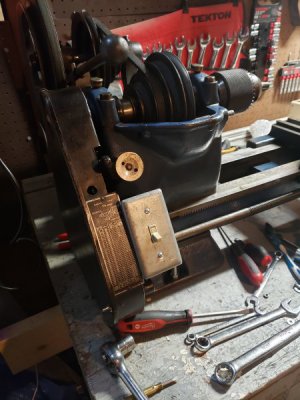
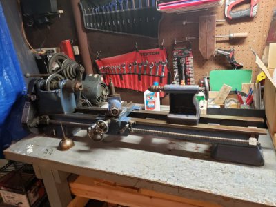
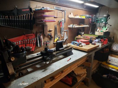
I do believe it is from 1936, and it was not optioned with back gears, it does have the babbit bearings. I have another motor that does have a plate and is 56 frame, so I'm pretty sure it is the same based on the dimentions. I'm not currently at home, and don't seem to have a picture of the number stamped on the bed, but I remember seeing it. Here are some pictures that I do have, and I'll add one of the bed this evening.

20190307_023051.jpg

20190304_083702.jpg

20190303_210447.jpg

20190124_221634.jpg
 
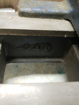
The last photo showing "948" is the bed casting number and most of the bed part number. The bed part number is probably 948B. The "48" means that the length of the ways is 48". Subtract 18" from the bed length of a 10" or 12" for the distance between centers. So your lathe is a 12x30 (12" swing and 30" max between centers).

The earliest parts manual that we have is for the 101.07381 (with back gears). The differences between the 101.0736x and the 101.0738x are no back gears and that the spindle cone pulleys on the 0726x's have the spindle indexing holes in them. And probably no hole for the direct drive pin. When you take the photo(s) of the serial number, also take 4 shots of the right face of the cone pulley, with the spindle rotated 90 degrees between shots.
 
The drawing that Robert mentions above is the drawing that I followed when making my pulley. The pulley works well.
 
Back
Top