Ball turning cutters

Maplehead

Registered
Registered
Joined
Feb 20, 2017
Messages
437
Hi All
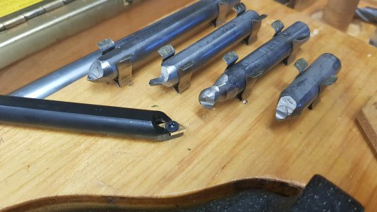
My research on ball/radius turning attachments seems to find that commercial attachments are only made for the smaller mini lathes. There's one old name out there, starts with an H but it evades me now, that looked like a commercial attachment for bigger lathes, but the jig is really expensive and only used models are left now. So it seems in the world of machining that ball turning jigs are mostly self made items. Hence the many "yet another ball turning attachment" threads. Well, for this post I'm hoping you all will upload pics of your ball turning cutters. I'm more interested in HSS than indexable cutters. So please post what you use and let me/us know how well they work for you. In mild steel, what depth of cuts can you make with them. What is your spindle speed? Any and all info is greatly appreciated.
P.S. I'm not including my cutter just yet because it sucks.
 
You are thinking of the Holdridge turning attachment, they will cut both male and female radii, I have one, and some years ago I was able to buy cutters for it, don't know about now.
 
I use the same bit that I would use in normal turning.
 
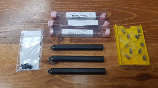
Here's the cutters I bought recently for my Holdridge, they're indexable though. They're pretty much the same as the indexables from Holdridge except these are $33ea rather than $80-$100ea. I just need to shorten 2 of them still. I was surprised to find these made by Mesa Tool & I'm glad.

Not that it matters unless you have a Holdridge but cutter height on these are on centerline of the shank rather than inline with the top of the shank like how most lathe tool bits are.

(In the background the tool bit on top & the one on bottom are the original carbide tipped Holdridge cutters)
20210611_184913.jpg
20210611_184553.jpg
 
I'm going to give this idea a shot.
.

Going to tweak it a bit, and use a shop made( slightly larger ) AXA4 tool holder, rather than clamp it in a standard tool holder. His has the centerline of the boring head hanging way out away from the tool post. Would like to keep it as close to the tool post as possible. Look forward to seeing other ideas.
 
Last edited:
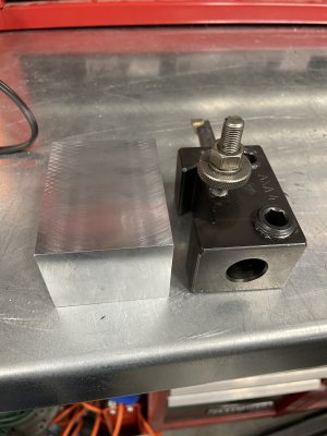
Got the basic block made for the tool holder. It's 7075. As seldom as it will be used, saw no point in using steel. It's .250" thicker and wider than a factory AXA4, so I'll hopefully have room to put an O-ring groove around the thrust washer recess on the cutter side face, to keep crap out of the thrust washer. The O-ring will also give a little drag to the tool, so it doesn't just flop around, if you let go of the handle.

IMG_8910.JPG
 
I'm going to give this idea a shot.
.

Going to tweak it a bit, and use a shop made( slightly larger ) AXA4 tool holder, rather than clamp it in a standard tool holder. His has the centerline of the boring head hanging way out away from the tool post. Would like to keep it as close to the tool post as possible. Look forward to seeing other ideas.

I used that same video as a guide for mine:
 
Ball_Makeing_Attachment_All_the_parts-WEB .jpg

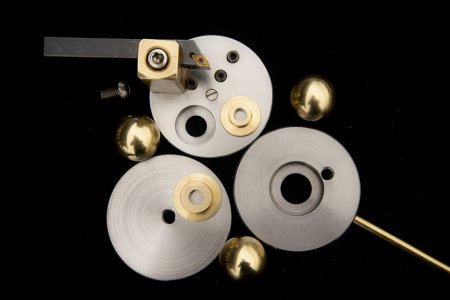
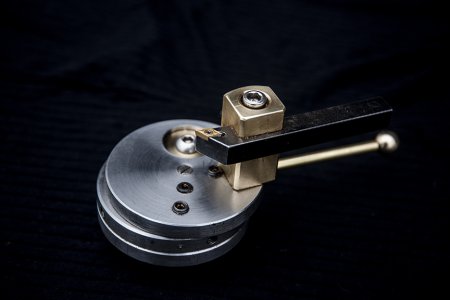
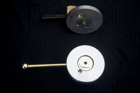
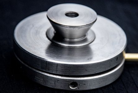
This is a ball turning attachment I made for my Boxford Model A 1955. I do not have a milling machine, so I had to design a ball cutter that could be made entirely on a lathe. So I came up with this design consisting of three stainless steel discs 10mm (3/8") thick and 80 mm diameter from a bar of scrap I happen to have. Although not essential I made the bearings from aluminium bronze (from a scrap dealer- the propellor shafts from old fishing boats, one 30mm diameter and the other 42mm. This is also what I used to make some 30mm balls shown here.

The compound slide is removed from the Boxford and the ball turner positioned in its place using the spigot shown in the last photo. So the bottom disk is fixed in place. The middle disc slides on top of it and provides the rotation for ball turning. It has a handle which surprisingly has a ball on the end!

The top disc pivots on an off-center axis and has the tool post mounted on it. The post can be moved to various different threaded holes and the surplus holes are plugged with grubby set screws to stop swarf getting between the discs. The position of the cutter, relative to the center of rotation, can be adjusted by sliding the top disc on the middle disc, and is then locked in place by tightening its pivot screw. It seems easy enough to adjust but not as easy as the conventional design with a milled slot, leascrew nut and handle with gib plates, but it is MUCH easier to manufacture.

I have made You Tube videos about how to use it which could be very useful, and how to make it. I hope it is of some use to others!


Ball_Makeing_Attachment_Fully_Assembled_Evan_Lewis_WEB.jpgBall_Makeing_Attachment_Main_Bearing_WEB.jpgBall_Makeing_Attachment_Spigot-WEB.jpg
 
Back
Top