Bob Shores Eagle Hit/Miss Engine Build Thread

ErichKeane

Making scrap at ludicrous speed.
H-M Lifetime Diamond Member
Joined
Aug 3, 2017
Messages
2,437
So, I just finished a PM#3 steam engine and have an appetite for another engine. Sadly, the steam engine spends its time in my garage (near the air compressor) so I don't get to play with it/admire it as much as I'd like. SO, I'm motivated by fuel engines. PMResearch has a air cooled fuel engine that looks awesome, but at $500, I'm not sure I want to get into it.

While looking around, I found this ebay listing: https://www.ebay.com/itm/Bob-Shores...-Kit-Drawings-and-Builders-Hints/254495200226. I did a bit of research on the Bob Shores engines and they look fairly cool, despite not having much in the way of a community around them (like the PM/Stuart stuff does). Well, I decided to bite the bullet and just build this one! I put in an order last night and will use this thread to try to keep track of my build progress!
 
Alright, a lot happened in the last two days while HM was down! So I'll split this into the two different days.

Day 1: Opening the package
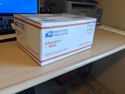
Day 1 was Monday. The only thing that happened is that I got the kit in the mail. It came REALLY quickly via USPS (seriously, it took just the weekend!). IMG_20200420_160127.jpg


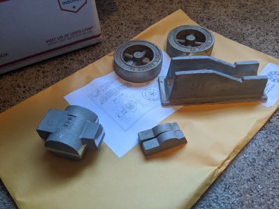
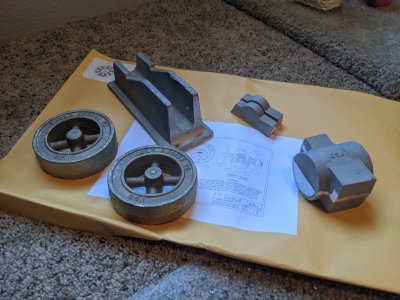
It was well packaged with a lot of wrapping paper, and included the 6 castings, and an envelope filled with plans and a build-guide, which is just sort of a set of "heres how I suggest doing this".
IMG_20200420_160344.jpgIMG_20200420_160340.jpg


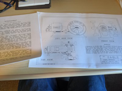
The plans are reasonably well written, though in order to save pages they seem to have stuffed each page with 3-4 parts intermingled. Its a little confusing at times if you aren't paying particular attention as it can be not clear what piece goes. Additionally, I would have loved some sort of tolerance markers in places. Compared to the PM-Research plans these are quite a bit more complicated, and lack a handful of details I would have loved to have.

IMG_20200420_160444.jpg


The castings themselves are a little rough. The PM-Research castings were just about dead-on in every dimension, but these are pretty wonky. You'll see in the next step that the cylinder casting is particularly so. There is also a lot of casting 'spatter' in the base itself, so I'm going to need to take a bunch of time filing these.
 
Day 2: Starting work on the cylinder casting.
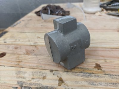
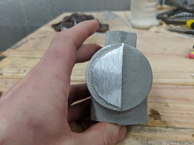
As mentioned previously, the cylinder casting is a little rough. The main circle is not quite round, and the top/bottom bosses are not square to it in any dimension! At least there is a bit of extra material in a couple of places that I was able to get it decent. There wasn't a good place to hold it in the vice, so I had to get a little creative to form my reference surfaces. At first, I tried to do a bunch of filing on the top boss, but I was doing a poor job keeping it square so I gave up and decided to just do it on the mill.

here is the cylinder casting (aluminum, the flywheels are bronze, everything else is Al):
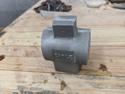
IMG_20200421_141223.jpgIMG_20200421_141226.jpgIMG_20200421_141231.jpg


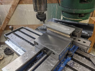
I decided to start by trying to set the top 'boss' as a reference surface, since it was the squarest thing on the casting. I held it in the vice by the cylindrical part, squared it horizontally as best as I could (which was surprisingly difficult, the cylinders bowed up quite a bit!). You can see some of my filing marks in this picture.
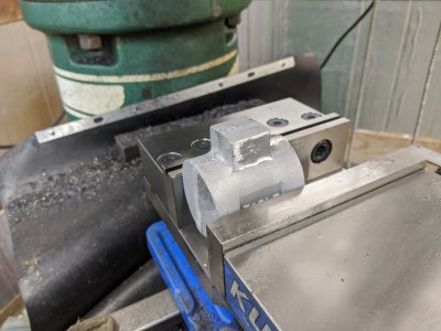
IMG_20200421_142639.jpg


I started by facing the top of the boss. I'll later shorten this quite a bit. The purpose of this boss is to be a coolant reservoir, so I'll need to remove the center of it.
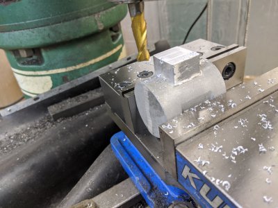
IMG_20200421_142915.jpg


Using the same endmill, I then went around the outside of the boss in an attempt to make it square. I'll have to spend some time cleaning up the casting/marks with a file/burr later, but since I wanted to use this for a reference surface this was necessary.
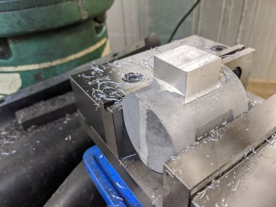
IMG_20200421_143258.jpg

Next, I milled the hole in the casting as deep as I could with this endmill. This needs to make it down into the 'cylinder' part, since there is an area in the middle of the cylinder where the bore is larger to allow water to go around the cast-iron bore liner. The plans tell me to make it .825 "square", but also tell me to make it .750 in one of the other pictures. I opted instead to choose a .100 wall thickness and did my math off of that. I did this by plunge cutting with the above endmill (which I hadn't realized has a step in it!), then slowly going around the outside at greater and greater depths. Other than the 'step' from the endmill, this turned out fine, and I don't really mind the step in retrospect. If I have to come back with a longer endmill at one point, I might make the hole a little larger. You can also see the final height, I took quite a bit off to make sure that my mill reached deep enough.
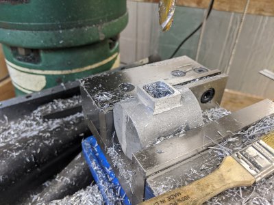
IMG_20200421_150504.jpg


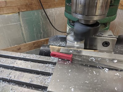
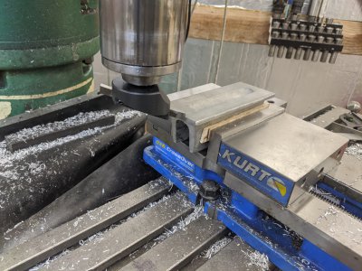
Next, I set it up as vertically as I could to try to face the cylinder. I used the top of the boss I just cut as a reference surface and used a square to try to get it as straight as I could. I had a lot of material to take off, so I started with my carbide face mill then used my (newly ground for only the 2nd time!) HSS fly cutter. There is A LOT of material to take off here, roughly 3/8 on each side to hit dimension. I did this by measuring the boss, then using a depth mic + math to figure out how large each had to be. I think I ended up 2 thou under, which I'm happy with.
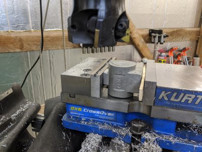
IMG_20200421_151545.jpg
IMG_20200421_152354.jpg

After I got both faces done, I moved to the bottom boss. This is simply to be the mounting area for the cylinder. Also, an interesting thing with this design, the cylinder sits 'low' and off center. It is measured off the bottom of this boss, so I chose to remove quite a bit of it. In retrospect, I sort of wish I'd flattened the bottom quite a bit more in order to get the cylinder more centered. I ended up taking off about 1/2" here! Check out the other pictures to see how tall this once was!. I started by face milling. I also went along the left/right sides to try to square those up, but I didn't have enough material to make it not so wonky. You can see in the pictures after this one that it isn't perfect.
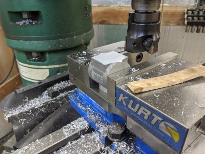
IMG_20200421_154516.jpg

I took it out of the vice to mark the center of the cylinder. You can see in this image how low that it has to be! Check out the front cover of the plans, this is actually a part of the design for some reason! Perhaps with the intent of increasing the water capacity?
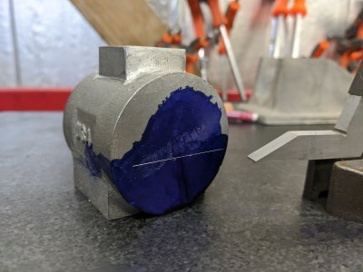

IMG_20200421_155718.jpg


It was at this point I realized I don't have a good way to measure the left/right of this, so I opted to use the top-boss for left/right, and used the bottom boss for the height. My scribe line and the DRO seemed to agree perfectly.
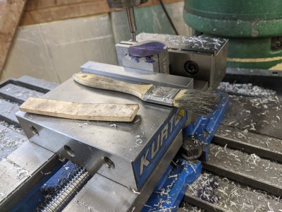
IMG_20200421_160255.jpg

I put a deep center drill for the cylinder bore itself, then used the DRO to drill the head-mounting holes. At the moment, they are not tapped as I have yet to get the correct tap in the mail :) I can always re-indicate for when I tap if necessary.
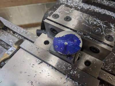
IMG_20200421_161400.jpg

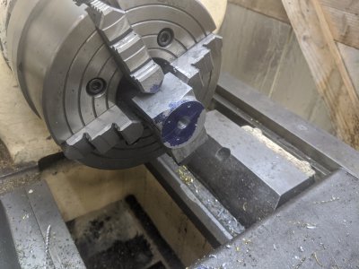
I used a piece of aluminum to protect the water reservoir , and popped it into my 4 jaw. I also used a parallel against the face of the 4 jaw, though I don't see where it was in this picture! I used the tailstock to press the part into the parallel, then tightened down the 4 jaw. I used the tailstock to confirm placement.
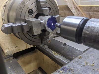
IMG_20200421_162148.jpg


Then, came drilling! I started with a 1/4" bit, then 3/8", and finally 1/2", which is my largest drill bit smaller than the final dimension. I'm supposed to hit 1.000" for the liner, plus mill a center section to 1.300" for the water jacket, so I've got quite a bit of time left for my boring job!
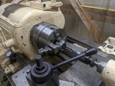
IMG_20200421_162339.jpgIMG_20200421_163441.jpg


I setup the largest boring bar I have that will fit into the hole currently, but I still haven't used it, so I don't have a tool ground! Looks like that is my next task! But alas, the dinner bell rang at this point, so the rest of this bore will have to wait until another day.
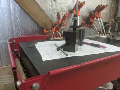
IMG_20200421_163727.jpg
 
Day 3: This was the boring part---

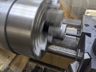
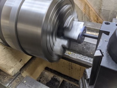
Alright, time to start cutting the bore! What a chore... Last time I ended up drilling up to 1/2 inch. Today, I need to get that up to 1 inch. I realized my boring bar actually wouldn't fit with a cutter on it, so I found one of my mill boring bars and used it to get the hole big enough, then switched to the boring bar from the last picture. I was conservative and took 20 thou (40 in diameter) per pass, at about 6 thou/rev. I reduced that to 3 thou/rev for the finishing pass.
IMG_20200422_133941.jpg
IMG_20200422_135449.jpg

I did a finish pass that measures exactly at 1", so I stopped! The bore LOOKS rough in the picture, but somehow feels perfect. Since about 2/3 is going to be cut out later today, and the other 1/3 filled with the cast iron liner, I considered this good enough. Here it is, and you can see the water reservoir poking through:
IMG_20200422_142955.jpg

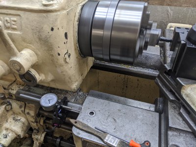
After that, I had to cut the water jacket. I put a 2" dial indicator on my ways, measured in 500 thou and cut 900 thou. This is a little oversized according to the plans, but I wanted to make sure I hit both sides of that reservoir. The 'far' side is a 90 degree, the near is about 30 degree transition, which you'll see in a bit. Thats because I was lazy and decided to just use the same boring bar.
IMG_20200422_144041.jpg

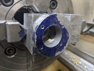
And here is the finished cut through the face! The part packed with chips is the reservoir, and you can see the rear "90" degree step.
IMG_20200422_144925.jpg

Finally, I cut a boss for the front side of the cast iron liner. No pictures, but the how should be obvious :)
IMG_20200422_150403.jpg

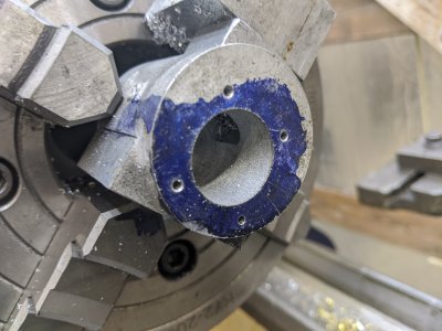
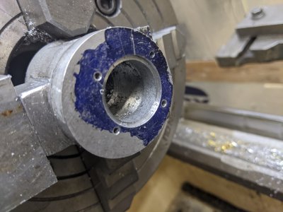
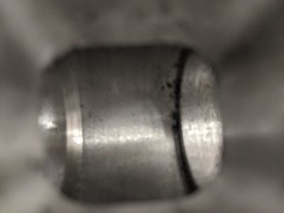
Here's both sides of the bore. After this picture set, I hit it with 500grit wet and dry paper on a piece of glass which polished the surfaces up nicely (and removed the dykem!).
IMG_20200422_150743.jpgIMG_20200422_150748.jpg

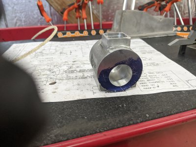
And here is one down the water reservoir. YOu can see the RHS is a 90 degree, the other side is an angle. I cannot imagine this will cause a problem, though if I change my mind it is easy enough to re-indicate this in the jaws and cut it from the other side.

IMG_20200422_150757.jpg


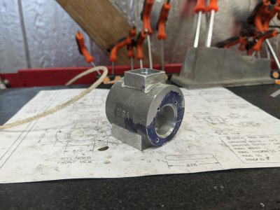
Alright, that part is done other than the threading the mounting holes! The paperwork suggests doing the bore liner and piston next, however I haven't received the CI from speedymetals yet, so I'll move onto the start of the frame.

This casting was ROUGH. There was 'splatter' and over-cast all over the place. I spent a while filing it reasonably clean, and even brought out the die grinder to clean up some spots.

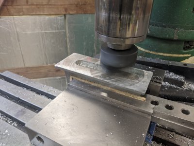
Putting it in the vice was an entirely additional problem! I had a tough time finding a reasonably 'square' surface, but the cylinder mounting flanges were close enough, so I used a pair of parallels to index those off of, then used my fly cutter to cut the bottom flat. It was FAR from it, and there was even a weird 'plug' (far side middle) that was about 50 thou proud of the rest. Flycutter made quick work of it!

IMG_20200422_152308.jpgIMG_20200422_152310.jpg
IMG_20200422_152723.jpg

Next step is going to be to flip that over, clamp it down, and mill the faces, but I ran out of time. I'll likely have to move my vise so the requisite grumbling of having to do that will have to happen first :) I also have to stop by a hardware store and pick up some 4-40 SHCS to attach the bearings for machining, but that is also a tomorrow problem!
 
Ah, just realized something. I cannot do much with the frame, since I don't have a way of bolting the bearing caps on! I don't have my tap in yet!

I've decided to put both the cylinder and frame in my "To be done" pile, and am going to find a new part to make tomorrow! Many/most of the parts seem to need materials or taps/dies to get any further, but I'll have to find a couple of parts I can still make :)
 
Really enjoying your build , I've always admired the models people do and hope some day I'll make one of my own , you descriptive details on setting up and challenges your overcoming are so helpful , thanks . Al
 
Really enjoying your build , I've always admired the models people do and hope some day I'll make one of my own , you descriptive details on setting up and challenges your overcoming are so helpful , thanks . Al
Thanks for the encouragement! After my last build thread didn't get much discussion and this one wasn't either I was concerned I was boring people :)
 
I am certainly not bored, I just do not post much.
Very much enjoying your set-ups & procedures.
Thanks.
 
Back
Top