Bob Shores Eagle Hit/Miss Engine Build Thread

Watching very closely as I bought this same kit after reading your first post last week. Unfortunately my kit has been stuck in Detroit and USPS says they don't know when it might leave there. Maybe in a week or maybe several weeks. Many people out with the virus and just a big mess there.

Ray
 
Watching very closely as I bought this same kit after reading your first post last week. Unfortunately my kit has been stuck in Detroit and USPS says they don't know when it might leave there. Maybe in a week or maybe several weeks. Many people out with the virus and just a big mess there.

Ray
Cool! It looks like a fun engine so far. It'll be nice to have someone else trying it too :)

I've had to order a lot of materials and tooling so far (this isn't an 'everything included like PM), so I suspect it'll be slower moving anyway.


Now, On to:

Day 4: A crazy idea, take 1

I was looking through the plans and trying to figure out what I had the materials and tools for, and came up with the crankshaft! In the design, it is a Stuart-style 3 segment + 2 web type crankshaft. However, after watching a bunch of Keith Appleton on Youtube (he does Stuart engine repairs!), I've come to hate this style. SO, I decided that I could do a 1 piece crankshaft! I calculated I need a 1.251" diameter rod in order to cut down the center and offset the other side for the crank part.

Unfortunately, my largest stock is 1.249". SO, Plan B: cutting BOTH sides offset! The nice part about this, other than it being more work, is that I can include the crank 'counterweights' like real crankshafts have (and I find super cool looking :) ).

First, cut the material a little oversized. It needs to be 5.062, I cut it to ~5 3/8.
IMG_20200423_144832.jpg

I then roughly centered it in the 4 jaw, and faced off each side. I didn't feel like swapping the 4 jaw off the lathe (since it was already there), and was going to need it in another moment anyway, so I just eyeballed center, then indicated it within ~10 thou.

IMG_20200423_145621.jpg


interestingly, I ended up leaving it 100 thou too long, though I wouldn't find that out until the very end. This one issue ends up being my downfall... (spoilers!)

IMG_20200423_150653.jpg

I used my height gauge and some V blocks to mark the center of the stock from 1 axis on both sides, and offset .213 (half the distance between crankshaft parts) in the other axis. Then, I used my tailstock to find that center point, and centered it up in the 4 jaw. I used that to cut "centers" for the long driveshaft part on each end.

IMG_20200423_152557.jpg

Now, its just turning between centers, taking off about an inch (down to .375), with an interrupted cut. This took HOURS. The first side went pretty easy:
IMG_20200423_154710.jpg
IMG_20200423_161120.jpg

On this side, I even got the length correct! I left it at .400" in diameter so that I could clean it up in a later op. The first side turned out great:
IMG_20200423_162946.jpg


Now, to the other side. Here, the first bad thing happened. My lathe dog was slipping constantly on this. I didn't have enough material to hold I think, and it was constantly just slipping, so I brought out my collet chuck. Next time (spoilers again!) I'll leave this at a much larger size, do the interrupted cut on both sides, then do the final dimensions on each after that.

IMG_20200423_165300.jpg

I got this down to size without further trouble (left it about 50 thou oversized), but got the center section (where the webs + small part of the crank will be) right on the money at .933. However, During this picture is when I realized that the plans were WRONG! This is actually supposed to be .925! Otherwise the math doesn't work. Bob apparently broke his CNC software designing this :) IMG_20200423_173834.jpg

However, it was at this point I also discovered that I'd left this 100 thou too long! I was able to put it back in the collet and trim the center down to .925. I even faced the length off to the perfect length. However, it left my center dcepth a LITTLE too short! SO, I opted to re-center drill it. My center drill snapped off (I think rubbing the live center might have work hardened it?) and I think bent the part. I was able to pick it out, but the end is kinda mangled (and a bolt needs to go in there).

I'll re-evaluate tomorrow, but I suspect I'm going to have to restart this part my next try.

Thats all the excitement for today! Glad you guys are enjoying this :)
 
Alright, thought a bit more about it, so I figured I'd float it to you guys a bit to make sure it isn't a mistake.

I think I'll still do the facing like before (this time get the length right!), and bluing/marking, but THIS time, mark both center points. THEN, center drill all 4 of them.

THEN, between centers, cut the middle section first! I didn't really have a good idea on how to do this the last time. I previously was going to do it with the 4 jaw, but holding .400 diameter stuff off center .438 seems really difficult. I think this way I can cut that part between centers! I'll have to be a little more careful with my layout (left/right on the part), and I think I have to grind a cutoff tool to reach that deep (I was going to have to anyway).

THEN, I can between centers cut each side down to ~900 thou (to get both sides round), then between centers cut each down to .375, thin an area for the threads, cut the taper, and cut the threads! Repeat on the other side :)

If I make this take long enough, I'll have the bearings show up (middle of next week) so that I can fit that dimension perfectly.
 
Great project! This is something that I've been working towards, and a kit seems to be a great way to learn many of the steps.

I'll be watching & learning as you go... :cool:
 
SO, I just went back and studied the dimensoins of the crank (as well as his description/suggestions for how to make it, and it is actually a 1 piece crank in the directions! Just that he makes it out of a .5x1" piece of bar, instead of round bar. I think I'll still use the round bar since I want the counterweights, but at least I'm kicking myself less for taking the hard way out :)
 
The advantage of using the .5 X 1.0 flat stock is you can use a band saw to cut most of the scrap stock away and save you some turning time. My dad made a 4 cylinder opposed engine years ago and I remember him making the crank with the flat stock.
I also am enjoying following your adventure with this project. Keep the photos and commentary coming.

Roger L

That makes a lot of sense! The plans weren't particularly clear, so I assumed it was the 5 piece style. I still love the look of the counter-weight crank, so I might still stick with it, though I'm pretty darn close to giving up. Which brings me to...

Day 5: Learning 1000 ways not to make a lightbulb...
After my failure yesterday, I went to the shop with renewed interest in making it work! I started by cutting the same material in the bandsaw, faced and cut to length, marked the ends and center-pointed, and did some layout. I remembered where I got this bar, I think it is probably A36 hot rolled steel (scrap bin at a welding shop).

I used the 4 jaw to setup the ends, and drilled centers. This time I found my MT4 dead center, which has a pointier tip, so I felt better about the accuracy.
IMG_20200424_140907.jpg

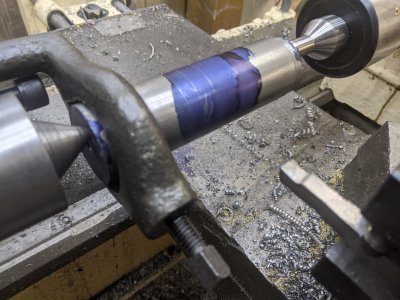
I set it up with the lathe dog, and started trying to cut the center piece first. This was quite an adventure. My cutoff tools REALLY disliked the interrupted cut. I ended up cutting a nearly full-width dovetail shaped cutter to try to get it. It made it through a lot of it (most of it was chewed away by cutoff tools). however, I think I had it slightly below center, and it caught. It ended up bending the stock when I was within 100 tho of being done. Try #2 done:
IMG_20200424_145140.jpg

At this point, I remembered I had 2 12" pieces of 12L14, 1.5"! This actually has the advantage that I can use the center of the bar, which makes the setup a little easier. I cut, faced, and center-drilled:
IMG_20200424_150006.jpg

I did my layout with blue. At the point, only the length is right:
IMG_20200424_154428.jpg

IMG_20200424_154428.jpg


I decided to cut the other centers with the mill and a wiggler. I again felt like this was more accurate than past attempts:
IMG_20200424_154757.jpg


Here is the dovetail tool I cut to try this. It is basically a 350 thou wide cutoff tool:) It did REALLY bad with the full-width cut, but I ended up using it a couple of times in the end. It failed, so i quickly switched to a cutoff tool or two:
IMG_20200424_161127.jpg

My standard type 'P' cutoff tool REALLY hated the interrupted cut and ended up flexing a bunch and cutting a really wacky/bad hole. However, it managed to remove a lot of the material. This cutoff tool removed quite a good amount of material, however there was one big negative: The right-side of the tool (after the relief) ended up digging into the good material on teh right. Fortunately it is stuff I would be able to take off later. Unfortunately, it wasn't going to matter...
IMG_20200424_162451.jpg

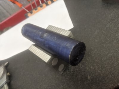
In this image, I've already got to my center diameter and moved to the other centers. You can see the gouge I was talking about earlier, but it is small enough I would be able to turn it off. My dovetail tool maanged to work really well and left a nice finish in the end, but I somehow ended up 10 thou undersized. I figured I have to make a bushing, I'd live with it.
IMG_20200424_164823.jpg

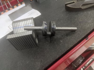
SO, I continued trying to turn down the right side to a smaller size. In retrospect, I should have put some material in the cutout to try to keep it from crushing, but past-me didn't think about it, and doesn't have superglue in the shop. I was healthily and happily taking a 50 thou cut, then seemingly double-dialed in a cut and started taking a heavy cut! It was making it through OK, and the chips looked fine so I let it keep going. Then, this happened:
IMG_20200424_164926.jpg

Ugg... Friday over.

I think I learned a bit today, so I am going to just try this again tomorrow. I'll likely do a few things different. First, I'll be more careful turning down the center, I think I'll try to grind a different HSS cutoff tool that is smaller than the ~300 thou (my 50 thou "ring cutter" tool did well, but died today :/) but big and strong enough to take the interrupted cut. That, or I'll try to make a pair of 'knife' tools (a LHS and RHS side) and just go back and forth cutting with those.

After that, I'll consider trying to pop a piece of scrap in the middle to stop my facing from breaking it off again. Alternatively, I might put it back in the 6-jaw at that point, and just cut the majority of it that way.

At least its the weekend tomorrow, so I have some good time to spend :)
 

Attachments

  • IMG_20200424_161125.jpg
    IMG_20200424_161125.jpg
    4 MB · Views: 15
  • IMG_20200424_135811.jpg
    IMG_20200424_135811.jpg
    3.6 MB · Views: 20
Day 6: Good enough... I finally get to take the win!

Yes, I finally got the piece done. I again started with 12L14, faced to length, and center drilled. Then I used the height gauge to set the crosshairs for the off-center one, and used the mill to center drill those ones. That left me with both sets of centers.

First, I used the offcenter holes to drill the offset piece. The secret ended up being these two tools. I used the pointy one sliding left and right to plunge, then the large cutoff-like tool to cut it flat/cut the sides. It went surprisingly easy, perhaps it was all the practice :)

IMG_20200425_141630.jpgIMG_20200425_141636.jpg

I'd hit the center about a thou small, which seemed good. Now, I wanted to rough cut the other parts. Last time, this caused problems because it snapped. This time, I used the chuck itself to hold it on the same side I was cutting. This let me take ~100+ thou diameter cuts and made short work of both sides. I turned them down to ~.400, a little extra room to clean up to .375.

IMG_20200425_141943.jpg
IMG_20200425_142939.jpg

This image here shows after the roughing cuts. You can also see where a poorly ground version of the pointy tool managed to nick away at the side of my web in the 'weight' area. This would turn out to ruin my plans for later.
IMG_20200425_144250.jpg


Back between centers, I turned down the webbings and the last ~25 thou for each side. Quite uneventful.

IMG_20200425_145548.jpg

Then there are two more features on the end of each, a 1/4-28 thread and a 20 degree taper. The 1/4-28 thread was easy enough to turn. The taper I ended up choosing to figure out how to use my attachment. Its not 20 degrees because my taper attachment maxes out at 17 degrees, but I feel like it was worth it to get to use the taper attachment!

IMG_20200425_153834.jpg

Both sides tapered! all the lathe work done! You can see on the left side where I thought about single pointing the threads. However, the tailstock live center hole is too big, and I would have ended up cutting into my live center :/ Oh well, I have a die coming, so I can fix it up later.

IMG_20200425_161441.jpg

Here I am cutting the counter weight webs. I used a HSS bit in betweeen the webs to stop me from crushing the center boss. I wanted to leave it quite a bit longer, but 2 things happened. First, I need to cut deep enough to get rid of that scar above. That took quite a bit. THEN, while doing this I must have done a poor job clamping it down, and half way through a cut the bit caught it and spun it upward a bit. After freeing it, the scar was pretty deep. I chose to cut the webs deeper than I otherwise would have in order to get rid of that mess.
IMG_20200425_162927.jpg


In the end, it looks about the same as if I'd cut it from bar stock. It took ~5 hours today to get this done, so I didn't feel like doing it again, so I think I'll live with it for a while. I'm happy enough with how it turned out. There IS a bit of counterweight to it, but not enough to overcome the boss.
IMG_20200425_165343.jpgIMG_20200425_165345.jpg

As you can see, it needs a little time with some scotchbrite and some files, plus some time with the die set, but overall I'm counting this as a win!
 

Attachments

  • IMG_20200425_144253.jpg
    IMG_20200425_144253.jpg
    3.9 MB · Views: 23
Alright, a short day today, but productive :)

Day 7: Cap n Taps!

I decided to do the bearing castings (and basically the last part for a while in the vise, since It'll need to come off when I clamp to the table). They are extremely oversized, and not even close to square in any direction! Fortunately they are oversized by quite a bit as well. I took the 'hump' and put it down, then got it as flat as I could. I then milled them to height:
IMG_20200426_141502.jpg
IMG_20200426_141504.jpg

I used wood blocks to keep it from moving while clamping, wich came in handy since I needed to take off more than I thought! Spec is .612, the parts were nearly an inch to start. SO, a lot came off!
IMG_20200426_142549.jpg

Then, I used that flat surface to square up the sides. These are REALLY oversized, but I only want to get them square enough to measure from and use. I'll cut to final width after I've got them on the frame.
IMG_20200426_143121.jpg

After squaring up the sides, I took to drilling the holes. I found the top of each, then used the DRO (used both INC and ABS modes, 1 for each!) to drill the holes. These are clearance for the 4-40 SHCSs that go through, plus clearance for the heads.
IMG_20200426_150718.jpg

Here they are all done and on the bench! Apparently some shmoo under the right one, as its not sitting flat.
IMG_20200426_151607.jpg

I stopped by Ace Hardware the other day to get 4-40 SHCS and found a set of 4-40 taps as well! The mail has been particularly slow the last few days, so the ones I was waiting on haven't arrived yet. SO, since I've still go the vise in place, I decided to use this opportunity to tap the cylinder for the head bolts:
IMG_20200426_153253.jpg

And that is it for the day! Not a huge amount of work(compared to yesterday!) but at least some parts done! My next step will be to pull the vise and start getting the frame done. Once I have the frame, I'll at least have a place to put some of these parts instead of just in a cardboard box! I also got the crankshaft bearings delivered, so I'll be able to get the crankshaft in place! I'm not sure what I'll do after that, but I'll be in a spot where I can work 'outward' on a couple of other parts.

I have some O1 tool steel coming for the valves and camshaft, so that is probably going to be a bunch of the next parts as well. Speedy Metals isn't living up to their name, so the cast iron for the bore liner and piston is still MIA.
IMG_20200426_154531.jpg
 

Attachments

  • IMG_20200426_144351.jpg
    IMG_20200426_144351.jpg
    3.5 MB · Views: 21
Day 8: Makin like a photo, getting Framed-

So, today I wanted to start working on the Frame! I had promised pulling the vise, but I didn't need to today. I'll need to tomorrow, but that is another day :) I DID get a bunch of materials in the mail today (Speedy metals pulled through!), so I'll have the stuff to finish the cylinder and piston, as well as a bunch more stuff.

However, first I wanted to finish the cylinder casting. All that was left was to drill the mounting holes on the bottom, so I did some measurements and got to work. However, this is where I learned that bore is about 50 thou off-center (I centered to the 'water' tank). I drilled the holes to keep the bore on center, and figure I'll file it smooth later. Not a huge operation, but time consuming, since I still manually tap:
IMG_20200427_150618.jpg

The next setup for the frame is one I've been thinking about for a long time. I realized however that one side of the frame was only a few degrees 'off' from straight, so I went to work with the file (and a height gauge for reference) and got the side flat. Since now I have a flat reference surface, I was able to use the vice form here out.

IMG_20200427_150753.jpg

I mounted the frame in the base on some paralells laying flat (since I already fly-cut the base) and went to work flattening the two mounting surfaces to height. The top set (for the bearing/caps) was REALLY bad, I ended up having to take off way more than I cared to, which makes the cylinder's mounting location pretty low. I'll probably see about fixing this at a later date.
IMG_20200427_151614.jpg

Here they are flattened, you can see the cylinder mounting area caused me to get into the angled part a little. At one point in the future I'll put this at an angle in SOMETHING (either on a angle plate, or tilt the head and use the flycutter/shell mill), but at the moment it'll work. The only dimension that really matters is the difference between the two surfaces, so its OK for now.
IMG_20200427_153811.jpg

Next I got to drilling the cylinder mount clearance holes. The bolts come up from the bottom and tighten. You drill all the way through with a #32, then relieve the back with a #14. On my 4th hole, without warning, the #32 snapped off in the hole. This ended up being... the worst. Details to come!

IMG_20200427_155435.jpg

However, since I have this fixtured, it is time to mount the bearing caps! All dimensions are off the center of the crankshaft bearing hole. I already measured/got those right on the bearing caps, so I used the broken drillbit from last picture to hold the bearing in place to find my X axis 'zero'. The Y axis is already right from when I centered the cylinder.

IMG_20200427_155620.jpg

I drilled and tapped all 4 holes (plus a bonus 5th hole to lock the camshaft in place, you'll see that in a future post!). Then mounted the bearing caps. Here you can see how darn oversized they are. Next step is to fix that!
IMG_20200427_162622.jpg

I ran an endmill on both sides of each until they were just about right with the sides. When I go to do finish work I presume I'll need to do some file work to get these looking right. I also used a center punch to mark the left one (and the frame itself) so that I get these in the right place. You can see the one on the left the bolt isn't centered. The casting has quite a bit of a 'bow' inward on that side, so the bolt is in the right place, the webbing isn't. It shouldn't effect anything other than my hatred for unevenness.
IMG_20200427_163312.jpg


Now to the counter drilling and getting the broken drillbit out. I started by counter drilling the other 3, and using their locations to figure out (with the DRO!) where the 4th was. I drilled until I hit the broken drillbit (or at least the drillbit started getting mad!). I then used a series of punches to knock it out, to no avail. THEN, I tried a carbide endmill, which I managed to chip the crap out of, but it mangled most of it. I kept going between the drill bit and a punch until I was able to poke it out. The hole is a little large, but that should be OK, since it'll be hidden.

While in this setup, I ALSO drilled/tapped a pair of 1/4-28 (not pictured) holes to mount this to a wooden board for the case. I need a place to mount the circuitry and the battery and the gas tank, so I'll likely do it in a box below! Also, i figure they'll come in handy for my next setup.
IMG_20200427_164149.jpg

And now the things that go together are bolted together! My next step will be to flip this sideways and cut the bearing holes + camshaft hole, which should finish up the frame. However, the dinner bell rang and I was done for the day :)

IMG_20200427_172107.jpgIMG_20200427_172111.jpg
 
Back
Top