Bob Shores Eagle Hit/Miss Engine Build Thread

I just got it yesterday but in the mean time I got a set of plans for a different engine and have been working on that.
I am watching this thread and understand why you are having problems with the castings. I am watching and learning.

Ray
 
I just got it yesterday but in the mean time I got a set of plans for a different engine and have been working on that.
I am watching this thread and understand why you are having problems with the castings. I am watching and learning.

Ray
Neat! I don't know how much of my problems are being spoiled by my PM kit, how many are just mediocre castings, or how many are just that I'm a pretty lazy/poor machinist :) I hope you post pictures of your other other project!
 
Day 12: Finishing the frame, making the camshaft-

I had a decent amount of time in the shop today, but only 1/2 of it was this project! See my soon-to-be-created thread (probably member projects?) for the quick one I'm working on in order to be able to do my next pair of parts.

Goal #1 today was to "finish" the frame, which is a bit of a lie since there are another 1/2 dozen or so tapped holes that go on it in a couple of places, but those are transfer drilled from other things.

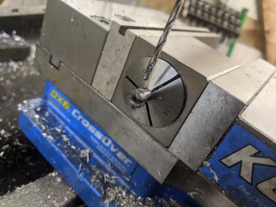
Since I made the frame 'square', I had a reference surface to use in the vise, so I used that to cut the bearing bores as my first task. I started by center drilling the top, then 1/4", then 3/8", then 1/2":
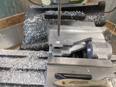
IMG_20200501_134616.jpg

Now that I had clearance, I center drilled the bottom half:
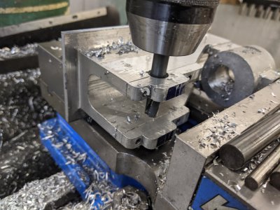
IMG_20200501_134931.jpg

Then I went to town with the boring head/boring bar. I cut until RIGHT on my size mark, though the bearings are a little loose since they are apparently a touch undersized. This isn't a problem, and I planned for it! The directions say they don't have to be 'tight', but I want them to be anyway.
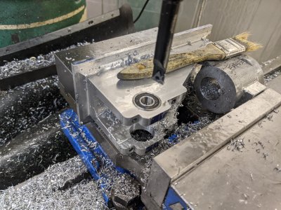
IMG_20200501_141526.jpg

Next I used the DRO to locate, center drill, drill, and ream the camshaft hole. The camshaft (made next) is a small piece of non-rotating tool steel that holes the gear in place (plus has another duty). Location is pretty critical, so I was glad to have the DRO and to do it in 1 setup.
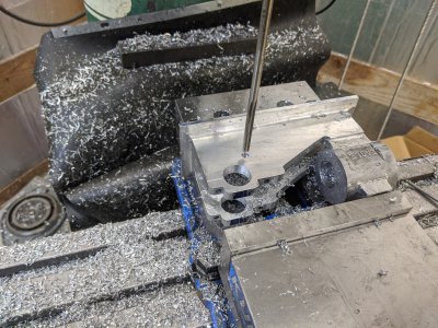
IMG_20200501_142030.jpg

I took about 3 thou off the bottom of each bearing cap, and it tightened the bearing fit right up. The camshaft is held in place with a set-screw, so this threaded hole (with the tap in it) is what holds it in place. I realized that my threads didn't make it to the bottom, so I tried to re-tap it. However, I found that my tap didn't make it to the bottom! It 'bottomed' out at the top of the tap. SO, I used my hand drill to cut #32 (clearance fit) about 1/8" down from the top until the bottoming tap peeked out into the hole. I re-reamed the hole quickly to clean it up, and counted this part done.
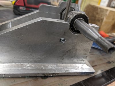
IMG_20200501_145009.jpg

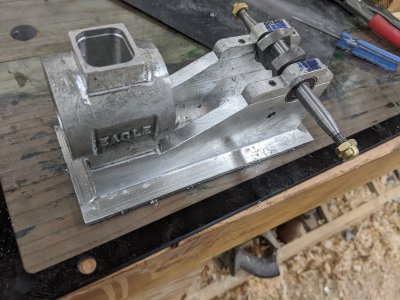
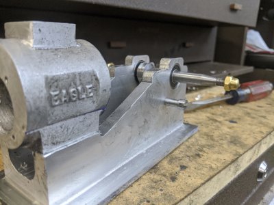
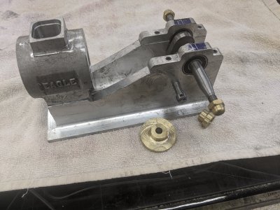
And here it is assembled! The plans call for making the Acorn nuts, but they were $8 for 25 on ebay, so I just ordered them.IMG_20200501_145416.jpg

Onto the next part, the camshaft! I chose this for 2 reasons: first, I want to start building the parts 'outward' from what I have, meaning I never want to make a part without a way of attaching it to the 'rest' from now on. It makes things easier to visualize, and tougher to lose. Second: I needed a win. The crankshaft and frame were such a discouraging pain, I went with a pretty simple part. My NEXT part is even scarier, so a quick and easy one felt like a good idea :)

Step 1 was to chuck up some 'drill rod' (O1 tool steel) and cut it into a 'pin' shape. .350 on the large end, .250 on the small. Length of the small end is given to 3 decimal places, but looking at the plans as long as it hits its minimum, I don't think it matters. I left it a little long, in part because my frame is a touch wider than the casting was. This part went easy enough!
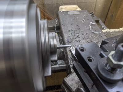
IMG_20200501_151119.jpg

Next, I needed a 1/8" slot down the middle that holds an arm later on. The width/centeredness is specified in the plans, but the 'depth' is not annoyingly enough. The 'instruction' sheets say "don't cut it too deep", but thats about all the info you get. I used the cad printout in the plans, measured that, and got it pretty close to what that was (though, the plans for this part are 1.5x!).
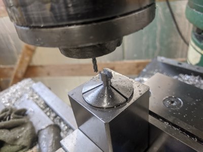
IMG_20200501_153852.jpg

There is a cross-hole for a 4-40 bolt here, though only 1/2 is threaded (the other half is clearance fit). SO, I drilled all the way through with my #43 as my threading, then 1/2 way through with the #32 clearance. Then tapped the bottom, and was all set with this part!
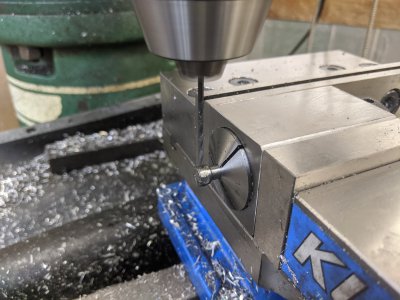
IMG_20200501_154230.jpgIMG_20200501_154354.jpg

And here the camshaft is installed!
IMG_20200501_155441.jpg

As I mentioned, my next parts require some additional tooling, so I spent rest of the afternoon starting on that. Hopefully I can get back to this soon!
 
Day 13: Starting the gears, cutting the cam:

So the plans tell you to start out with a pair of gears from "Small Parts". I couldn't find them literally anywhere. Boston Gear, McMaster, Amazon, Ebay, nothing. The hubs sizes just aren't available. SO, I get to make them from scratch.

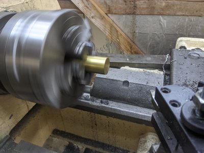
Today, i made the blanks. First I faced a big brass rod:
IMG_20200502_122246.jpg

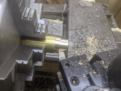
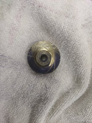
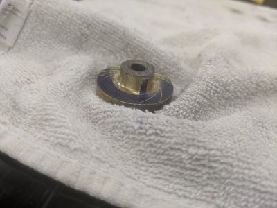
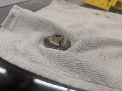
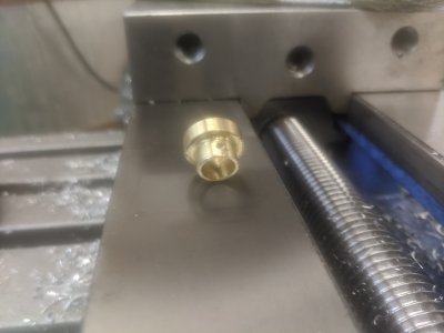
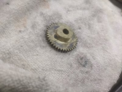
The first thing I made was the camshaft gear, which is the bigger of the two. The plans had the OD wrong (I did the math, and confirmed it on the internet!), the OD is supposed to be 1.3125 instead of 1.375. I cut the OD for the teeth, then cut the OD for the hub (.720) for 1/4" protrusion. I then drilled and reamed to .250.
IMG_20200502_124049.jpg

I parted, flipped it, and faced the back.

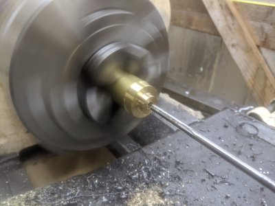
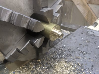
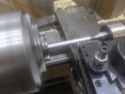
Then I started the crankshaft, which has a .687 OD. I ended up just going to town with my lathe :) Below is a stopped lathe working on a .200 diameter cut! It actually hit the left shoulder at the edge of the cut a little and cut .250 for a second. The lathe obviously didn't seem to care in such a soft material!
IMG_20200502_130300.jpg


The plans call for taking the .250 ID and drilling it to .374 to fit on the crankshaft. Instead, I drilled/reamed it as a part of this cut to .375. If I need to, I'll use loctite or a set screw if necessary.
IMG_20200502_131922.jpg

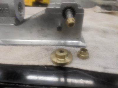
Then I cut and faced it like the other, and here are the two together. Just about where they will end up living some day :)
IMG_20200502_132434.jpg


I don't have the chuck for my rotary table yet (I ordered an MT2 scroll chuck thing), so I can't cut the teeth. However, I can cut the cam on the cam gear! First, here is the jig.. It is simply a piece of stock with a hole drilled/tapped slightly offcenter. You then bolt the gear to it, and cut the hub down .140" on the diameter. You then unbolt and move it about 5 degrees. You just keep doing this until you've cut about 230 degrees (plans say all but 130). I scribed an index mark on the tool, and 2 130 degrees apart on the gear.
IMG_20200502_133941.jpg

Here you can see it in progress! First, you can see I hit the bolt at one point :) I also got about 1 thou into the back of the gear a couple of times as you can see. It was otherwise unexciting, albeit tedious:
IMG_20200502_140242.jpg
IMG_20200502_140247.jpg

IMG_20200502_141415.jpg


And here it is off the lathe/jig! I might put it back into the lathe at one point to see if I can face the back off a little. However, you can see the cam fully shaped! I spent a few seconds with a file getting rid of the sharp spots, and cleaned it up:
IMG_20200502_141712.jpgIMG_20200502_141718.jpg

IMG_20200502_141720.jpg

And thats it for today!
IMG_20200502_142008.jpg
 
Day 14: The cylinder liner

I didn't get to do any work yesterday as we went and hung out with the inlaws all day. Also, I didn't cut the gear teeth as I'm still waiting for my MT2 chuck to hold a rod to cut them with. hopefully it'll show up tomorrow so I can get the gears cut finally!

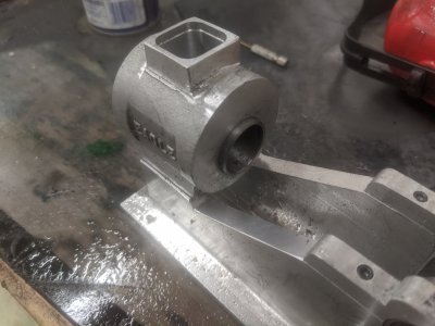
But today, I wanted to do the cylinder liner. This is a cast-iron part that goes into the aluminum cylinder, and holds the piston. The water jacket sits in the aluminum around it. It has a little bit of a boss to fit into the cylinder to keep it in place (at 1.125), and the rest of the OD is 1.000 to fit in the cylinder. My inner cylinder measurement was actually a few thou under that, so this ended up being a touch smaller.

I picked up some 1 3/8" cast iron rod from Speedy metals, chucked it up, and went to town! Order of ops was a bit of a question here, but I decided to just go for it. At this point, you can see I've done the OD and the little 'step'. Everything is a little longer than necessary. Then i center drilled, then drilled up to 1/2" (my largest drillbit smaller than the bore).
IMG_20200504_143530.jpg

I was able to polish this in about 20 seconds, and got a fabulous finish on it! I'm a little sad that the OD of this is going to be hidden. It is darn-near shiny! Anyway, then I started the boring. I used a HSS insert cutter out of my boring head, which wasn't particularly happy about this, however its what I had that fit in the bore. Then, once it fit, I used my boring bar with a HSS bit set-screwed in for the last ~10 thou + finishing passes. I did about 4 spring passes to get it cleaned up, then used a brake-cylinder-hone to hone the bore (rather than the tool he suggests).
The inside is pretty shiny as well :)
IMG_20200504_154551.jpg

After parting, I faced the head-side first, then realized I was about 90 thou too long. I got lucky and the head side flange actually fit in the 'teeth' in my chuck. So it was pretty easy to put back in the chuck :) A little facing, and some deburring.

IMG_20200504_160930.jpg


And here it is in place! It was a 'tap fit', I had to tap it with a wood mallet a little to get it to go all the way in.
IMG_20200504_161254.jpg

The measurements in the plans have it sticking out the back a little. I have no idea why! BUT, this is made to dimension.
IMG_20200504_161258.jpg

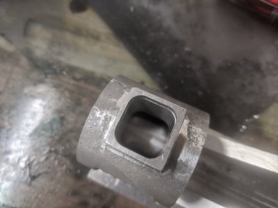
And now you can see the water-jacket thing. Water goes in the hole and stays between the aluminum casting and the liner.
IMG_20200504_161300.jpg
 
Day 14: The cylinder liner

I didn't get to do any work yesterday as we went and hung out with the inlaws all day. Also, I didn't cut the gear teeth as I'm still waiting for my MT2 chuck to hold a rod to cut them with. hopefully it'll show up tomorrow so I can get the gears cut finally!

But today, I wanted to do the cylinder liner. This is a cast-iron part that goes into the aluminum cylinder, and holds the piston. The water jacket sits in the aluminum around it. It has a little bit of a boss to fit into the cylinder to keep it in place (at 1.125), and the rest of the OD is 1.000 to fit in the cylinder. My inner cylinder measurement was actually a few thou under that, so this ended up being a touch smaller.

I picked up some 1 3/8" cast iron rod from Speedy metals, chucked it up, and went to town! Order of ops was a bit of a question here, but I decided to just go for it. At this point, you can see I've done the OD and the little 'step'. Everything is a little longer than necessary. Then i center drilled, then drilled up to 1/2" (my largest drillbit smaller than the bore).
View attachment 323257

I was able to polish this in about 20 seconds, and got a fabulous finish on it! I'm a little sad that the OD of this is going to be hidden. It is darn-near shiny! Anyway, then I started the boring. I used a HSS insert cutter out of my boring head, which wasn't particularly happy about this, however its what I had that fit in the bore. Then, once it fit, I used my boring bar with a HSS bit set-screwed in for the last ~10 thou + finishing passes. I did about 4 spring passes to get it cleaned up, then used a brake-cylinder-hone to hone the bore (rather than the tool he suggests).

The inside is pretty shiny as well :)
View attachment 323258

After parting, I faced the head-side first, then realized I was about 90 thou too long. I got lucky and the head side flange actually fit in the 'teeth' in my chuck. So it was pretty easy to put back in the chuck :) A little facing, and some deburring.

View attachment 323259


And here it is in place! It was a 'tap fit', I had to tap it with a wood mallet a little to get it to go all the way in.
View attachment 323261

The measurements in the plans have it sticking out the back a little. I have no idea why! BUT, this is made to dimension.
View attachment 323262

And now you can see the water-jacket thing. Water goes in the hole and stays between the aluminum casting and the liner.
View attachment 323263

That was a big step you got done! Looking like an engine! Great work.
 
That was a big step you got done! Looking like an engine! Great work.
Thanks! I've got a couple of pretty interesting/new tasks coming up that are going to be interesting. First of course is gear cutting, which I've never done. Then when I'm making the head, I have to make valves/valve guides, which seems difficult/interesting. Then, I actually am going to make springs for this! I found a pack of cheap piano wire (basically 6ft of all the sizes for ~$10!), so I'm going to give it a shot, I've never done it. There is a carburetor to make, and even an exhaust.

I'm leaning toward making the head/stuff as soon as I'm done with the gears. There is a governor assembly and breaker assembly on the crankshaft that I don't totally understand yet, so I'm thinking I'll start working on 'the other end' for a while.

I'd not realized when I bought this kit how ambitious it is. This is an absolute 10x of work/skills from the PM#3 kit I finished. There are way more parts, and much more complex parts. Additionally, there will be a decent amount of electrical at the end before this will even run.

I've got a feeling my 'build thread' here is going to last quite a few pages as a result, I'm not even 1/4 of the way through yet!
 
No work today, I spent the day inside cooking Lasagna today instead! I DID get the MT2 2" 3 jaw in the mail as well as the spark plug, so I have what I need to do the gears AND the head!

Hopefully tomorrow I'll get the gears cut and start on the head.
 
Day 15: Gears!

First, I decided to put a set-screw into the small gear, since it is supposed to be fixed to the crankshaft. I don't know if that was a good idea, since I only got a couple of threads(it is REALLY thin wall here...) but if it doesn't work I guess I can use loctite on this one. I DID do #4-40, so I'd hoped I could get enough threads:
IMG_20200506_141126.jpg


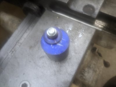
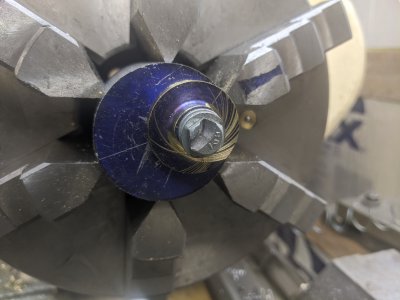
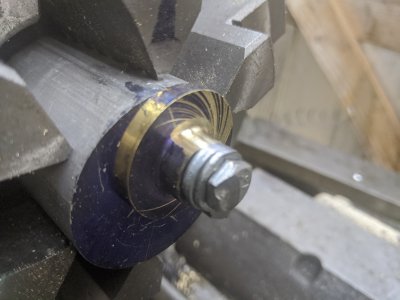
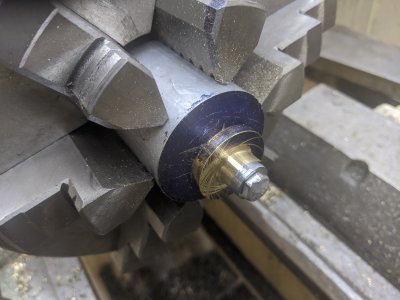
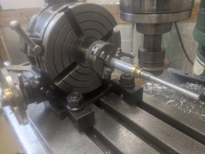
Next I started to make an arbor out of 1/2" aluminum for the gear cutting. The idea was that I'd turn it down to .375 (for the crankshaft gear), then thread the end for a nut to hold it into place. This has 2 problems; First, the washers/nuts I used were bigger than the gear, and would get cut too.
Second, it turns out that the hex die for 3/8-16 ended up mangling this shaft a whole bunch! It wasn't anything close to straight anymore! I scrapped the part and tried again with a shorter threaded section, but got the same problem:
IMG_20200506_141635.jpg

This is the second try at the arbor. It ended up being that the gear was a good press-fit on the shaft anyway, so I risked it. I think it turned out alright!
IMG_20200506_154935.jpg


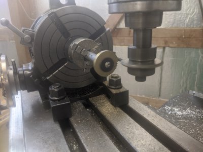
Then, I started on the camshaft gear. However, about 3 teeth after this I realized I forgot to change out the gear cutter! I was cutting the wrong thing! I swore a bunch, then recut the gear blank on the lathe.
IMG_20200506_162640.jpg


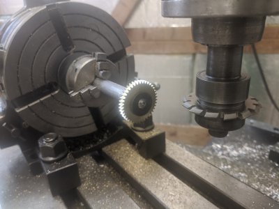
I didn't take pictures of the recutting of the blank, but it went simply. Also, I was then able to cut the gear with the RIGHT cutter fairly quickly!
IMG_20200506_170739.jpg


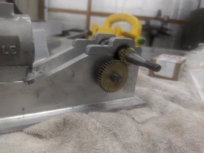
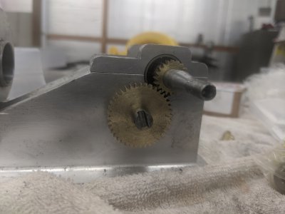
Here's the mesh! Its perhaps a touch loose, but I'm not sure why. All my measurements were within a few thou, and I used the DRO for depth of cut. Both ODs still measure the right size, and I used the machinist handbook to get the depth measurement of .068. They run smoothly though, which is all that matters.

IMG_20200506_171139.jpg


Next, I had to recut the cam, which took a little bit of time, but wasn't too bad since I already had the process well learned. Took about an hour to recut the cam.
IMG_20200506_174338.jpg

Back on the engine:

IMG_20200506_174548.jpg

A quick video spinning the crankshaft to test meshing. It worked perfect! The crankshaft is NOT out of round like it looks at the end, the threaded area just is a bit of a optical illusion.

Anyway, good enough for now... I might come back in the future and have to recut one or two of these to get them to mesh better, but at the moment I'm happy.
View attachment VID_20200506_174601.mp4
 
Day 15: Gears!

Here's the mesh! Its perhaps a touch loose, but I'm not sure why. All my measurements were within a few thou, and I used the DRO for depth of cut. Both ODs still measure the right size, and I used the machinist handbook to get the depth measurement of .068. They run smoothly though, which is all that matters.

Anyway, good enough for now... I might come back in the future and have to recut one or two of these to get them to mesh better, but at the moment I'm happy.
Congrats! I always tell my wife to PLEASE leave me along when I cut gears. You get in a rhythm and don't want to be disturbed.

There are web sites out there that offer calculators and the formulas for center to center distance and other gear dimensions. I didn't find one (very quick search) with a handy calculator for diametral pitch though they are bound to be out there. According to Engineers Edge, your diameter pitch of 16 converts to a Module pitch of 1.588 (Module = 25.4 / Diametral Pitch).

Don't quote me on the numbers, IF I did the math correctly, the center distance on a 20-tooth to a 40-tooth 16-diametral pitch gear set should be 1.876". Your gear blanks should have an OD of 1.375" and 2.626".

Here are the steps going through the chart and formulas from the web sites below:

Module = 25.4 / 16 or 1.588 module

D1= 20 (teeth) x 1.588 = 31.76 mm (reference diameter according to khkgears site - circular diameter depending on your nomenclature)
DA1 = D1 + 2*Module = 31.76 mm + 2*1.588 = 34.936 mm blank OD = 1.375"
D2 = 40 (teeth) x 1.588 = 63.52 mm
DA2 = 63.52 mm + 2*1.588 = 66.696 mm blank OD = 2.626"

Center to center distance = (D1 + D2) / 2 = (31.76 mm + 63.52 mm) / 2 = 47.64 mm = 1.8756"

Of course, I took the LONG way around converting from diametral to module and back again.

Your drawing probably gives X, Y for the center points, not a straight line dimension. The straight line or center to center distance is:

CD = square root ( (X1 - X2)^2 + (Y1 - Y2)^2 )

Hope this confuses you appropriately! You probably already have the charts and calculations if you've gotten this far and don't need the references, but just in case. . . At least you can confirm if the apparent looseness is in the original design or not.

Bruce


Back
Top