BollAero 18 Diesel engine

Canuck75

Active User
H-M Supporter Gold Member
Joined
Jan 1, 2014
Messages
233
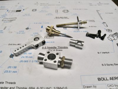
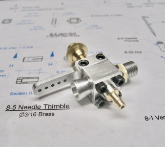
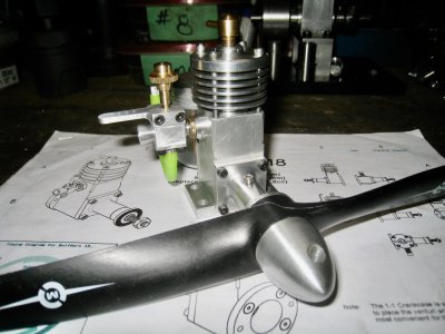
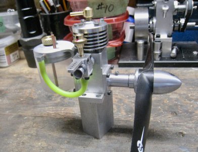
Am looking at the BollAero 18 diesel as my next model engine project. Have been studying the plans and have a question I hope an H-M member familiar with the BollAero 18 might answer. It has to do with the placement of the transfer ports in the cylinder sleeve (page 6 of the drawing set) which are 45 degrees each side of the exhaust port (90 degrees apart). I know the transfer ports allow the pressurized charge from the crankcase to the cylinder when the piston is at a certain point. In other words transfer is based on vertical movement of the piston (timing) and not on where the ports are in the horizontal. As designed the cutouts for the transfer ports are pretty close to the exhaust port making sealing the crankcase a little more problematic. I can't isolate that portion out of the blueprints so hope someone can understand and answer from my description.

Can the transfer ports be spaced 180 degrees apart thus 90 degrees from both the intake and exhaust ports?
 
Last edited:
The transfer ports can be placed anywhere,however ,the principle of the Schnuurle loop scavenge may be compromised ,causing the majority of the charge to go straight out the exhaust port....The modern two cycle was invented by C.J.Day in 1895,and it took a very long time to get beyond his basic work with marine diesels ,and produce the high per cc outputs we are familiar with,when we see a 100cc bike on the back wheel taking off at the lights
 
Thanks for your reply.
I understand what you are saying about the scavenge activity and how the incoming charge assists that process.
The top/bottom of the transfer holes are .097"/.183" from the top of the block. The top/ bottom of the exhaust hole is .0315"/.2085" from the top of the block. The top of the piston is .170" below the top of the block at BDC. So in this design the piston never completely uncovers the transfer ports or the exhaust port. The exhaust port is opening for .065" of piston down travel before the transfer ports start to open. The ports continue to open and overlap (timing) as the piston travels to BDC and then during up travel. The exhaust port is the last to close. With the incoming charge entering so close to the exhaust port a lot of fuel will just slobber out the exhaust port as it joins exhaust flow. Would less fuel not be lost if the transfer ports were further from the exhaust port?? In the microsecond that the piston takes before it covers everything up again on the upstroke I don't know if that would make a difference, but it would seem so.
Sealing of the cylinder sleeve to the block is the other big issue, maybe even whether the engines runs or not. Spreading the distance between the holes theoretically should help plus extremely close fit of the parts.
Have also been wondering if making the transfer and exhaust holes oval would help so that they are fully exposed at BDC?
Tricky questions.
Oh, when you were mentioning the performance of small engine bikes, you are right, but in that case exhaust tuning has a great deal to do with power output.

Maybe will screw up the courage to experiment a bit.
 
Last edited:
Im not familiar with your design,but small 2/s typically are either deflrctor piston or loop.....with deflector ,you can put the ports anywhere,but with loop ,must be in the correct location...and shape too...So assuming the design is sound ,to deviate may result in a motor that wont run properly.
 
John.k
Again thanks for your reply.
Have been doing more reading and see that the BollAero is indeed a Schnuerle loop scavenging design. Also found an explanation of why the positioning of the ports near the exhaust works.
So, without and further fanciful ideas of changing things, will continue the build exactly as designed and hopefully have a running model in the end.
 
Last edited:
Have just finished the BollAero 18 engine.
Won't know for sure how it runs until we get over the CoronaVirus restrictions and can get out to get the ingredients for the diesel fuel. Might be a couple of months.
Made a couple of changes. The prop driver used 4 segments to fit into the cavities on the back of the 12" x 6" prop, and, also fitted a controllable throttle body vice just using the depicted full open venturi fuel system. Some other minor changes. Just used some pictures as guidance for the fuel system design. My wife provided a cosmetic spray can top for the tank.
Biggest challenge was the close tolerances for the piston and the cylinder sleeve.
For the rest of it I'll just let the pictures do the talking.

For my next project have decide to try and make another Ron Cherrich offering called the "Fig Tree Pocket Twin". Ron attributes the engine to Russell Watson-Will of Fig Tree Pocket, Brisbane, Australia, although Russell also attributes some aspects of the engine to others. It's also a diesel of 4.00 ccm capacity and much more difficult to make. Looking forward to the challenge.
 

Attachments

  • IMG_9134.jpeg
    IMG_9134.jpeg
    468.1 KB · Views: 26
  • IMG_9142.jpeg
    IMG_9142.jpeg
    554.7 KB · Views: 21
  • IMG_9145.jpeg
    IMG_9145.jpeg
    747.5 KB · Views: 19
  • IMG_9167.jpeg
    IMG_9167.jpeg
    2.2 MB · Views: 21
  • IMG_9175.jpeg
    IMG_9175.jpeg
    1.2 MB · Views: 21
  • IMG_9177.jpeg
    IMG_9177.jpeg
    1,021.3 KB · Views: 20
  • IMG_9197.jpeg
    IMG_9197.jpeg
    1.5 MB · Views: 21
  • IMG_9199.jpeg
    IMG_9199.jpeg
    1.3 MB · Views: 23
  • IMG_9200.jpeg
    IMG_9200.jpeg
    1.1 MB · Views: 21
  • IMG_9201.jpeg
    IMG_9201.jpeg
    1.4 MB · Views: 20
  • IMG_9202.jpeg
    IMG_9202.jpeg
    1.1 MB · Views: 21
  • IMG_9206.jpeg
    IMG_9206.jpeg
    1.3 MB · Views: 21
  • IMG_9224.jpeg
    IMG_9224.jpeg
    1.8 MB · Views: 23
  • IMG_9231.jpeg
    IMG_9231.jpeg
    985.1 KB · Views: 23
  • IMG_9234.jpeg
    IMG_9234.jpeg
    1.4 MB · Views: 29
  • IMG_9237.jpeg
    IMG_9237.jpeg
    1.1 MB · Views: 32
Last edited:
Back
Top