Brass .250”

COMachinist

Active User
H-M Supporter Gold Member
Joined
Sep 10, 2013
Messages
562
Hi All.
I am in need of a brass .250” 9 tooth spear gear for a RV auto pointing over the air dtv antenna drive. The gear that is on it a plastic gear and it has a few deformed teeth that locks it up when pointing. The antenna is 300.00+ usd to replace and this antenna. This is out of warranty of coarse and is the 3rd one that I have had on the RV. We only watch tv for local weather and news when traveling so can’t see dropping another $300+ for another one. I don’t have a clue on how get the specs on this gear and the company won’t give that info out. So I have 90:1 rotory table and hss bits I can grind a cutter I think. I have only repaired gears not sure of making one. I think brass will work better than a plastic gear an this seams to be a problem with the teeth deforming.
Any help is appreciated and thanks.
CH
 
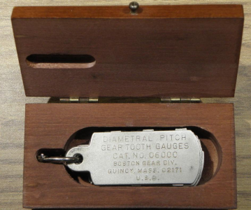
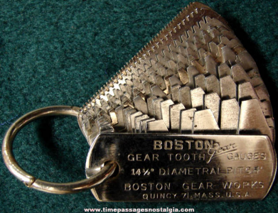
The proper way to determine the gear specs is with some gauges, like these:

1624826671079.png 1624826709962.png

I got mine from Boston gear. It has both 14 and 20 degree pressure angle "leafs".

However, there are other ways:
1) take some measurements and pictures of the gears you have and post them. That will help us determine first if they are metric or not, and second the pitch or module. Not just the worn gear, but the one it mates with as they need to be of the same "family".
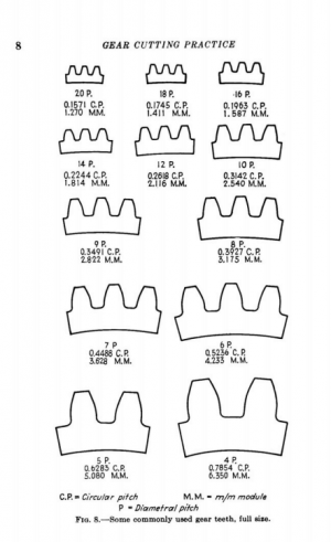
2) a number of old books used to have some full-size drawings of gear profiles that you could compare a gear against
I will see if I can find some to post.

I realize that you're after something stronger than plastic, but let me throw out another option.
The CAD software Fusion-360 has a simply gear generator that can make gear models for a 3D-printer.
I have made and used a few.
The real beautiful aspects of this route are the effort and cost.
A model can be generated in a few minutes and printed in a couple hours for under a few dollars in plastic filament.
Several spares could be made for a "lifetime supply".
Different printers can reach temperatures that allow tougher, high-impart plastics.
ABS or Nylon are likely better for your purpose.

-brino
 
Last edited:
Ok thanks for the info and links. I as best I can figure the Dp is equal to 44. It will take some presion tool grinding to get a useable profile on it to cut the teeth. I plan to use some 360 brass to make the gear I need.
Thanks again
CH
 
Diametral pitch and/or modulus can be determined by measuring the O.D. in mm and dividing by the number of teeth + 2 for metric gears or dividing the number of teeth + 2 by the O.D. measured in inches. The result should come out to a nice decimal fraction or very close to one for metric gears or a nice whole number or close for inch gears.

Determining pressure angle is a bit more tricky as the difference is subtle. A visual comparison will usually do it. SDP/SI is a good source for gears and the have technically correct drawings of their products.

A 44 D.P. gear doesn't appear to be a standard diametral pitch. Calculating as a metric gear, it would be a mod .577 which is not close to a common modulus. It is possible the the manufacturer decided to use a non standard gear. I'm not sure how they would deal with cutting such a gear but with injection molding, this would be possible. As to a metal gear, the best bet would be to have one cut with wire EDM. There are other possibilities such as sintered metal printing but more expe4nsive for a one-off part.
From a 1-off perspective, it would be easy enough to just cut it with a dividing head, right? You can grind an HSS cutter for this by eye reasonable easily. Click-spring recently showed a bunch of videos on how to create a 4-tooth gear-cutter that is accurately the right pressure angle/pitch based on how the cutter-for-the-cutter is made. I can't seem to find it right now though...
 
From a 1-off perspective, it would be easy enough to just cut it with a dividing head, right? You can grind an HSS cutter for this by eye reasonable easily. Click-spring recently showed a bunch of videos on how to create a 4-tooth gear-cutter that is accurately the right pressure angle/pitch based on how the cutter-for-the-cutter is made. I can't seem to find it right now though...
Yes, it could be done. A 1/4 inch gear would require some finesse though. I had thought about using my CNC mill with the fourth axis. The limit for gear diameters is a straight rack where the cutter tooth profile is a simple rhombus. Using the CNC capability, it would be possible to cut an accurate gear with that profile. Another thought that I had was to use a small diameter end mill or a slitting saw offset by the pressure angle to accomplish the same task. Here is a video re: using a CNC and 4th axis to cut small gears.
Perhaps some clock makers can chime in.

One saving factor is that the application is slow speed and more than likely a gear that is less than perfect would work fine.
 
Well I can’t beleive it but I made one that works for now. I ground a 1/8” hss tool to fit the driven gear tooth profile then mounted it in a small fly cutter holder and cut 9 teeth that did not fit. Turns out the gear is like 6.47 which turned out to be .2547”od tried again and it fit well enough to move the antenna. It worked. Good thing my rotary table is a 90:1 so 10 turn per it may not be perfect but it is now working like a new one. Saved 300.00+ this time. Thanks for the info.
CH
 
Back
Top