Bridge Crane build

Argh! That is one approach. But it has significant downsides. Medical staff fear lawsuits alright. This leads to them wanting to follow procedures that are most defensible in court, rather than what they professionally think has the best outcomes for you. And every one else suffers for the fallout of this mentality.
Following that logic, a lawyer who has a serious medical issue might be between a rock and a hard place.
 
Following that logic, a lawyer who has a serious medical issue might be between a rock and a hard place.
He has the option to keep his mouth shut and not assume that the hospital and the courtroom warrant the same approach. I've known many compassionate lawyers who would have no problems in that situation. What I don't like is stupid idiots who make other people miserable for their own benefit and others detriment. But perhaps we're off-topic enough that this conversation is inappropriate for HM. I'm going to pigeonhole further discussion on this topic in this thread. I started the tangent so that's on me.
 
Last edited:
I don't understand, why minimal pendulum length. A full length brings more energy and more sway. As the piece transitions to the end of that swing, is a factor of length and mass... at least from what I remember (memory is suspect, my chips may have popped).
 
I don't understand, why minimal pendulum length. A full length brings more energy and more sway. As the piece transitions to the end of that swing, is a factor of length and mass... at least from what I remember (memory is suspect, my chips may have popped).
I'm assuming the load is moving at the same speed as the overhead when the "sudden stop" occurs. So the energy inherent in the load is determined by the speed of motion. The pendulum length determines how quickly that load imparts impact on the crane structure. Zero length gives maximum impact over the least amount of time.
 
The reality is that the static load on my bolts will be zero.
From a visual on your photographs, your base bolts seem to be 5/8 or 3/4 - Grade 5 will be more than adequate. Besides if the post has a sudden bending moment brought on by a suddenly stopped load, each of the bolts are in tension, not shear. In fact the upper track to the posts are in the same boat.

As I tried to suggest, over-specified fasteners can be a source of failure. If your bottom plates are 1/2" or greater, THEN I'd use Grd 8 bolts, because your plates are much more rigid than the tensile strength of your Grd 5 fasteners can contain. Even so, Grade 5 is actually stronger than you need unless you have 20' posts and stop a 1 ton load very suddenly...

On thing to keep in mind is that the track becomes a rigid structure sharing the load on all the posts (somewhat) equally. So all bolts in all the base plated contribute to resist stopping forces to one degree or another. The only way to know the exact forces is to conduct an FEA on the entire system, with all connections partially constrained by known or assumed friction factors. You cannot pay me enough to go back to those days... My brain hurts thinking of the SIMULA programs I had to write.
 
your base bolts seem to be 5/8 or 3/4 - Grade 5 will be more than adequate.
Yep, I'm designing with 5/8" grade 5 bolts. Those plates will get grouted once leveled, so you're right, dynamic tension only.

Yeah, I think trying to do FEA on this level is not warranted and simple good practice with a healthy margin is sufficient. (I wouldn't make that assumption/comment if it weren't my shop.)
 
--Blame my bad memory. Grade 5 is around 100KPSI to 120KPSI and grade 8 is 150KPSI range. I had a brain fart. I used to know all this off the top of my head! Age or last years brain injury. It has to be one of those.
 
floorplan1.jpg

I'm convalescing after my recent adventures, but thinking about this crane some more.
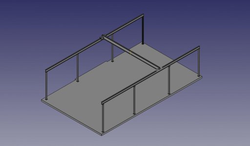
If you look at the image, it is almost intuitive that this structure needs some cross bracing. I intended from the start to incorporate such, sometimes pounding things into FREECAD just isn't worth the effort. I want to include what is a classic Y or trident bracing at the top of each post. There is also an assembly issue. The posts are currently free standing pillars. So the simple approach is to hoist each rail into position, bolt it to the top of the posts, then install the crossbracing, and the bridge beam. Each rail is about 500 lbs. And the bridge is about 500 lbs. Working on hoisting these into place while other pieces are suspended somewhat haphazardly overhead is, uh, stupid? So I need to come up with plan to do this methodically.

The catch is I'd like to have the structure somewhat less than rigid so that once everything is initially bolted together loosely, I can level the entire structure, probably using the same machinist level that I use to level lathe beds. And square it (rails parallel), etc.

Occurred to me that if I use a couple of large turnbuckles, I can use those in place of a few of the Y post braces to achieve this, reasonably secure for assembly and adjustable until I square, level, grout and torque everything down. Now 16 of those gets to be pricey, but I can replace turnbuckles with fixed braces (basically a piece of say 1/2" x 1" flat HRS) bolted to the turnbuckle attachment points, and get away with quite a few less. Do I need those braces at every intersection? Well, probably not. I do intend to eventually go with a full height X brace in one place under each rail. But I'm not a steelworker, so I won't be welding/drilling bolt tabs into the structure after it is assembled. I'm just going to throw in more brace attachment points than I strictly need so that I have some options. So I need to go fab up a bunch of bolt tabs to weld on. That is just a single cut on the horizontal bandsaw, a drilling op, and cleanup on the belt grinder for each tab. 32 of them, coming up. Just as soon as I'm finished with post-hospitalization bed rest.
 
Last edited:
Randal, could you assemble is sections? By that I mean install the temporary Turbuckle X between to of the posts on one side. Lift the top rail and secure in place then replace the turnbuckles with Y Bracing and then move to the next section. Would this be too ridged to still be able to adjust the height after it was all in place? Maybe level each section as you go. Does it really need to be as level as a lathe bed? I have no experience with but enjoy the thought experiment :)
 
Last edited:
View attachment 441217

I'm convalescing after my recent adventures, but thinking about this crane some more.
If you look at the image, it is almost intuitive that this structure needs some cross bracing. I intended from the start to incorporate such, sometimes pounding things into FREECAD just isn't worth the effort. I want to include what is a classic Y or trident bracing at the top of each post. There is also an assembly issue. The posts are currently free standing pillars. So the simple approach is to hoist each rail into position, bolt it to the top of the posts, then install the crossbracing, and the bridge beam. Each rail is about 500 lbs. And the bridge is about 500 lbs. Working on hoisting these into place while other pieces are suspended somewhat haphazardly overhead is, uh, stupid? So I need to come up with plan to do this methodically.

The catch is I'd like to have the structure somewhat less than rigid so that once everything is initially bolted together loosely, I can level the entire structure, probably using the same machinist level that I use to level lathe beds. And square it (rails parallel), etc.

Occurred to me that if I use a couple of large turnbuckles, I can use those in place of a few of the Y post braces to achieve this, reasonably secure for assembly and adjustable until I square, level, grout and torque everything down. Now 16 of those gets to be pricey, but I can replace turnbuckles with fixed braces (basically a piece of say 1/2" x 1" flat HRS) bolted to the turnbuckle attachment points, and get away with quite a few less. Do I need those braces at every intersection? Well, probably not. I do intend to eventually go with a full height X brace in one place under each rail. But I'm not a steelworker, so I won't be welding/drilling bolt tabs into the structure after it is assembled. I'm just going to throw in more brace attachment points than I strictly need so that I have some options. So I need to go fab up a bunch of bolt tabs to weld on. That is just a single cut on the horizontal bandsaw, a drilling op, and cleanup on the belt grinder for each tab. 32 of them, coming up. Just as soon as I'm finished with post-hospitalization bed rest.
Randal, I think you would be chasing your tail trying to level it with a machinists level. That's a lot of accuracy for something that will probably start deflecting and lose much of that instantly. Just an opinion. I do agree about keeping it loose until you get it all together, but you can probably start tight , then loosen it so that it's self constrained and as true as it will get without your further intervention.

I think 5 gal concrete pails a bunch of them with eyebolts in the concrete will be your friend in trying to setup and secure the iron. That, or some holes in that nice new floor.
 
Back
Top