- Joined
- Feb 27, 2012
- Messages
- 45
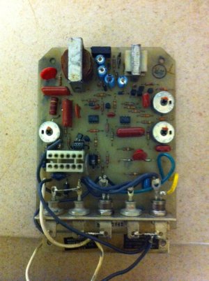
I have a bridgeport mill with the factory power feed unit. A while ago, a piece of bar stock fell over and demolished the fuse holder on the control panel of the power feed. No problem, I bought a replacement fuseholder and set about replacing it. When I took the lower panel off to access the wiring of the fuse holder, I found 2 things I didn't expect. First was a loose wire nut, just laying inside there. The second was a wire attached to the fuse holder that was no longer attached to anything else. It probably came loose when I took the panel off the bottom of the drive. It did not appear to have solder on the end but also did not appear to have been wire-nutted together, either. There are no bundles of wires missing their wire nut and I can't figure out where this wire was originally connected. I have traced the power path in from the cord, thru the on-off switch to the power-on light and to the fuse holder. Obviously, the wire in question is the power lead FROM the fuse TO the circuit board. Not obvious is where it was attached. Intuitively, I think it should be attached to the one of the diodes which are mounted on the heatsink on one edge of the circuit board. But, I'm also smart enough to not go and stick a hot wire someplace to see if it works. The circuit diagram in my manual (M-105H), page 46 shows the wire (which is black, BTW) going to an unlabelled point on the circuit board. The schematic, on page 47, is beyond my electronic expertise to comprehend, but it seems to START where the black and white power leads come into the circuit board, neatly bypassing the external portion of the control, including the on-off switch, power-on light and the fuse. Can anyone tell me where that power wire is supposed to be fastened? I'm getting really tired of cranking that X-axis. Thanks.
If you're an electronics whiz, or just curious, send me a message with your e-mail address and I will send you scanned images of both the circuit diagram and the schematic.
If you're an electronics whiz, or just curious, send me a message with your e-mail address and I will send you scanned images of both the circuit diagram and the schematic.


