I got a Sino DRO a number of years ago and installed the X axis on my Burke Millrite, but never got around to the Y axis due to the complexity of the angled castings, then discovered the scale was broken in the middle and could not be salvaged. So, I was using 1 DRO axis and dials on the other for a number of years. I finally got around to ordering a Y axis scale and trying to figure out how best to mount it.
I decided to install the X axis scale on the front of the table since it has a T slot already there, and I can mount the reader head in the spot for the table stop. I don't have a power feed installed, so that hasn't been a problem, but I may install a power feed at some point and will need to figure out a work around. I decided against mounting on the back of the table since that would have taken up too much of the Y axis travel, and since this is a smaller mill to be begin with, I did not want to take up any additional travel.

There is not much info out there to use as ideas, and what I found was people making brackets at the required angles. I didn't want to do that, so I came up with an adjustable bracket instead. Luckily the casting near the knee ways looked to be straight, so I only needed one adjustable bracket. I decided on an angle bracket mounted to the machine with slots to allow in and out as well as horizontal twist adjustment. To allow for vertical adjustment, I used a steel rod in the horizontal adjustment block with a mounting block on the other end that could twist in the vertical direction. I forgot to get pictures of this before the scale was mounted.


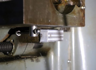
Once this was installed, I needed a way to attached the reader to the Y axis. There is a bracket driven by the Y axis leadscrew that is in a good location to use, but it is a rough casting.

To use this, I would need to machine the casting flat, and then drill and tap two holes for the reader bracket. That sounded like too much work, so I decided to use a method that was even more work! I made a mounting block that I was going to attach to the leadscrew bracket with JB Weld. I have the DRO unit mounted to the mill by using a piece of angle aluminum attached using JB Weld and it has held for several years, so I was confident this would work as well.

That sounds easy, but then I needed a way to hold it in position while the epoxy cured. I made a contraption the sits flush against the Y axis saddle with an adjustable piece holding the mounting block in place. One of my woodworking clamps was the right size to use to hold while the epoxy cured. At this point, removing the leadscrew bracket and machining it was sounding like a better idea. After curing overnight, the block was firmly in place and it was time to fabricate the brackets to drive the reader.


I had some brackets from the Sino scales, but they have a different hole spacing than the Ditron scale I bought as a replacement. So I needed to modify one of the Sino brackets to work with the Ditron angled bracket, and fabricate a piece from the mounting piece I just installed to the other bracket pieces. Finally success! Everything is dialed in the vertical and horizontal directions and the reader head moves nice and smoothly. Finally I can use the DRO as intended. Well, not so fast. My father-in-law bought me this DRO on one of our trips to China and the store gave him a lathe unit when I asked for a mill unit. When he tried to exchange it, they told him it was no different and they would not take it back. So, I have a unit with lathe features and none of the mill features I wanted. That will be corrected this week when the new DRO unit arrives and this DRO gets moved to the lathe.


I decided to install the X axis scale on the front of the table since it has a T slot already there, and I can mount the reader head in the spot for the table stop. I don't have a power feed installed, so that hasn't been a problem, but I may install a power feed at some point and will need to figure out a work around. I decided against mounting on the back of the table since that would have taken up too much of the Y axis travel, and since this is a smaller mill to be begin with, I did not want to take up any additional travel.
There is not much info out there to use as ideas, and what I found was people making brackets at the required angles. I didn't want to do that, so I came up with an adjustable bracket instead. Luckily the casting near the knee ways looked to be straight, so I only needed one adjustable bracket. I decided on an angle bracket mounted to the machine with slots to allow in and out as well as horizontal twist adjustment. To allow for vertical adjustment, I used a steel rod in the horizontal adjustment block with a mounting block on the other end that could twist in the vertical direction. I forgot to get pictures of this before the scale was mounted.
Once this was installed, I needed a way to attached the reader to the Y axis. There is a bracket driven by the Y axis leadscrew that is in a good location to use, but it is a rough casting.
To use this, I would need to machine the casting flat, and then drill and tap two holes for the reader bracket. That sounded like too much work, so I decided to use a method that was even more work! I made a mounting block that I was going to attach to the leadscrew bracket with JB Weld. I have the DRO unit mounted to the mill by using a piece of angle aluminum attached using JB Weld and it has held for several years, so I was confident this would work as well.
That sounds easy, but then I needed a way to hold it in position while the epoxy cured. I made a contraption the sits flush against the Y axis saddle with an adjustable piece holding the mounting block in place. One of my woodworking clamps was the right size to use to hold while the epoxy cured. At this point, removing the leadscrew bracket and machining it was sounding like a better idea. After curing overnight, the block was firmly in place and it was time to fabricate the brackets to drive the reader.
I had some brackets from the Sino scales, but they have a different hole spacing than the Ditron scale I bought as a replacement. So I needed to modify one of the Sino brackets to work with the Ditron angled bracket, and fabricate a piece from the mounting piece I just installed to the other bracket pieces. Finally success! Everything is dialed in the vertical and horizontal directions and the reader head moves nice and smoothly. Finally I can use the DRO as intended. Well, not so fast. My father-in-law bought me this DRO on one of our trips to China and the store gave him a lathe unit when I asked for a mill unit. When he tried to exchange it, they told him it was no different and they would not take it back. So, I have a unit with lathe features and none of the mill features I wanted. That will be corrected this week when the new DRO unit arrives and this DRO gets moved to the lathe.