The project is to make a worm gear set to drive an instrument, a telescope. I have settled on a worm gear design. I have a piece of Acme rod for the worm drive and am planning on cutting the gear with a tap. I am ready to cut the first test gear and after watching several videos I realized the effective diameter of the gear is not the raw outside diameter of the blank, but rather the resulting diameter after the tap as removed material sufficient to seat the threads. I am using a 1/2 inch drive and tap. The gear is 1/4 inch thick. I believe the tap will reduce the effective diameter of the gear blank as it cuts teeth. Does anyone have experience with designing this? Is there a reference?
-
Welcome back Guest! Did you know you can mentor other members here at H-M? If not, please check out our Relaunch of Hobby Machinist Mentoring Program!
You are using an out of date browser. It may not display this or other websites correctly.
You should upgrade or use an alternative browser.
You should upgrade or use an alternative browser.
calculating effective gear diameter
- Thread starter dansawyer
- Start date
Worm gear set dimensions are available for FREE on the interweb
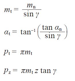
Table 4.22 presents the relationships among worm and worm wheel with regard to axial plane, transverse plane, normalplane, module, pressure angle, pitch and lead.
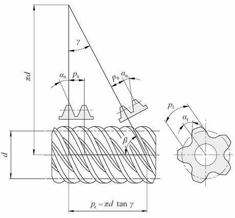
Fig. 4.16 Cylindrical worm (Right-hand)
Table 4.22 The relations of cross sections of worm gear pairs
Reference to Figure 4.16 can help the understanding of the relationships in Table 4.22. They are similar to the relationsin Formulas (4.16) and (4.17) in that the helix angle β be substituted by (90 deg – γ). We can consider thata worm with lead angle γ is almost the same as a helical gear with helix angle (90 deg – γ).
(1) Axial Module Worm Gear Pair
Table 4.23 presents the equations, for dimensions shown in Figure 4.16, for worm gears with axial module, mx, andnormal pressure angle αn=20°.
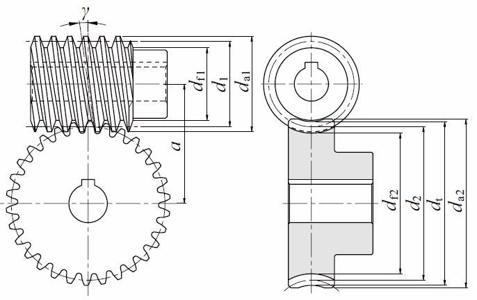
Fig. 4.17 Dimentions of cylindrical worm gear pair
Table 4.23 The calculations for an axial module system worm gear pair
NOTE 1.
Diameter factor, Q, means reference diameter of worm, d1, over axial module, mx.
Q=d1 / mx
NOTE 2.
There are several calculation methods of worm wheel tip diameter da2 besides those in Table 4.25.
NOTE 3.
The facewidth of worm, b1, would be sufficient if: b1=πmx (4.5 + 0.02z2)
NOTE 4.
Effective facewidth of worm wheel bw=

So the actual facewidth of b2 ≧ bw + 1.5mx would be enough.
(2) Normal Module System Worm Gear Pair
The equations for normal module system worm gears are based on a normal module, mn, and normal pressure angle, αn=20°. See Table 4.24.
Table 4.24 The calculations for a normal module system worm gear pair
NOTE : All notes are the same as those of Table 4.23.
(3) Crowning of the Tooth
Crowning is critically important to worm gears. Not only can it eliminate abnormal tooth contact due to incorrectassembly, but it also provides for the forming of an oil film, which enhances the lubrication effect of the mesh. Thiscan favorably impact endurance and transmission efficiency of the worm mesh. There are four methods of crowning wormgear pair :
(a) Cut Worm Wheel with a Hob Cutter of Greater Reference Diameter than the Worm.
A crownless worm wheel results when it is made by using a hob that has an identical pitch diameter as that of theworm. This crownless worm wheel is very difficult to assemble correctly. Proper tooth contact and a complete oil filmare usually not possible.
However, it is relatively easy to obtain a crowned worm wheel by cutting it with a hob whose reference diameter isslightly larger than that of the worm.
This is shown in Figure 4.18. This creates teeth contact in the center region with space for oil film formation.
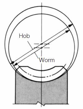
Fig.4.18 The method of using a greater diameter hob
(b) Recut With Hob Center Position Adjustment.
The first step is to cut the worm wheel at standard center distance. This results in no crowning. Then the worm wheelis finished with the same hob by recutting with the hob axis shifted parallel to the worm wheel axis by ±Δh. This resultsin a crowning effect, shown in Figure 4.19.
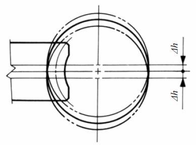
Fig.4.19 Offsetting up or down
(c) Hob Axis Inclining Δθ From Standard Position.
In standard cutting, the hob axis is oriented at the proper angle to the worm wheel axis. After that, the hob axisis shifted slightly left and then right, Δθ, in a plane parallel to the worm wheel axis, to cut a crown effect on theworm wheel tooth.
This is shown in Figure 4.20. Only method (a) is popular. Methods (b) and (c) are seldom used.
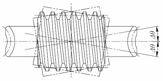
Fig. 4.20 Inclining right or left
(d) Use a Worm with a Larger Pressure Angle than the Worm Wheel.
This is a very complex method, both theoretically and practically. Usually, the crowning is done to the worm wheel,but in this method the modification is on the worm. That is, to change the pressure angle and pitch of the worm withoutchanging base pitch, in accordance with the relationships shown in Equations 4.25 :

In order to raise the pressure angle from before change, αwx, to after change, αx , it is necessary to increase theaxial pitch, pwx, to a new value, px, per Equation (4.25). The amount of crowning is represented as the space betweenthe worm and worm wheel at the meshing point A in Figure 4.22. This amount may be approximated by the following equation:

Where
d1 : Reference diameter of worm
k : Factor from Table 4.25 and Figure 4.21
Table 4.25 The value of factor k

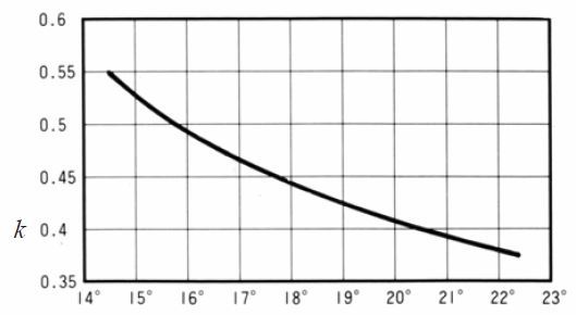
Axial pressure angle αx
Fig. 4.21 The value of factor (k)
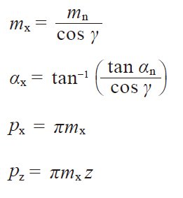
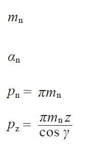
Table 4.22 presents the relationships among worm and worm wheel with regard to axial plane, transverse plane, normalplane, module, pressure angle, pitch and lead.

Fig. 4.16 Cylindrical worm (Right-hand)
Table 4.22 The relations of cross sections of worm gear pairs
| Worm | ||
| Axial plane | Normal plane | Transverse plane |
| 
| 
|
| Transverse plane | Normal plane | Axial plane |
| Worm wheel |
Reference to Figure 4.16 can help the understanding of the relationships in Table 4.22. They are similar to the relationsin Formulas (4.16) and (4.17) in that the helix angle β be substituted by (90 deg – γ). We can consider thata worm with lead angle γ is almost the same as a helical gear with helix angle (90 deg – γ).
(1) Axial Module Worm Gear Pair
Table 4.23 presents the equations, for dimensions shown in Figure 4.16, for worm gears with axial module, mx, andnormal pressure angle αn=20°.

Fig. 4.17 Dimentions of cylindrical worm gear pair
Table 4.23 The calculations for an axial module system worm gear pair
| No. | Item | Symbol | Formula | Example | |
| Worm (1) | Wheel (2) | ||||
| 1 | Axial module | mx | Set Value | 3 | |
| 2 | Normal pressure angle | ( αn ) | ( 20 deg ) | ||
| 3 | No. of threads, no. of teeth | z | Double Thread (R) | 30 (R) | |
| 4 | Coefficient of Profile shift | zt2 | – | 0 | |
| 5 | Reference diameter | d1 d2 | ( Qmx) NOTE1 z2mx | 44.000 | 90.000 |
| 6 | Reference cylinder lead angle | γ | 
| 7.76517 deg | |
| 7 | Center distance | a | 
| 67.000 | |
| 8 | Addendum | ha1 ha2 | 1.00 mx ( 1.00 + xt2 ) mx | 3.000 | 3.000 |
| 9 | Tooth depth | h | 2.25 mx | 6.750 | |
| 10 | Tip diameter | da1 da2 | d1 + 2ha1 d2 + 2ha2 + mx NOTE2 | 50.000 | 99.000 |
| 11 | Throat diameter | dt | d2 + 2ha2 | – | 96.000 |
| 12 | Throat surface radius | ri | 
| – | 19.000 |
| 13 | Root diameter | df1 df2 | da1 – 2h dt – 2h | 36.500 | 82.500 |
Diameter factor, Q, means reference diameter of worm, d1, over axial module, mx.
Q=d1 / mx
NOTE 2.
There are several calculation methods of worm wheel tip diameter da2 besides those in Table 4.25.
NOTE 3.
The facewidth of worm, b1, would be sufficient if: b1=πmx (4.5 + 0.02z2)
NOTE 4.
Effective facewidth of worm wheel bw=

So the actual facewidth of b2 ≧ bw + 1.5mx would be enough.
(2) Normal Module System Worm Gear Pair
The equations for normal module system worm gears are based on a normal module, mn, and normal pressure angle, αn=20°. See Table 4.24.
Table 4.24 The calculations for a normal module system worm gear pair
| No. | Item | Symbol | Formula | Example | |
| Worm (1) | Wheel (2) | ||||
| 1 | Normal module | mn | Set Value | 3 | |
| 2 | Normal pressure angle | αn | ( 20 deg ) | ||
| 3 | No. of threads, No. of teeth | z | Double (R) | 30 (R) | |
| 4 | Reference diameter of worm | d1 | 44.000 | – | |
| 5 | Normal profile shift coefficient | xn2 | – | – 0.1414 | |
| 6 | Reference cylinder lead angle | γ | 
| 7.83748 deg | |
| 7 | Reference diameter of worm wheel | d2 | 
| – | 90.8486 |
| 8 | Center distance | a | 
| 67.000 | |
| 9 | Addendum | ha1 ha2 | 1.00 mn ( 1.00 + xn2 ) mn | 3.000 | 2.5758 |
| 10 | Tooth depth | h | 2.25 mn | 6.75 | |
| 11 | Tip diameter | da1 da2 | d1 + 2ha1 dt2 + 2ha1 + mn | 50.000 | 99.000 |
| 12 | Throat diameter | dt | d2 + 2ha2 | – | 96.000 |
| 13 | Throat surface radius | ri | 
| – | 19.000 |
| 14 | Root diameter | df1 df2 | da1 – 2h dt – 2h | 36.500 | 82.500 |
(3) Crowning of the Tooth
Crowning is critically important to worm gears. Not only can it eliminate abnormal tooth contact due to incorrectassembly, but it also provides for the forming of an oil film, which enhances the lubrication effect of the mesh. Thiscan favorably impact endurance and transmission efficiency of the worm mesh. There are four methods of crowning wormgear pair :
(a) Cut Worm Wheel with a Hob Cutter of Greater Reference Diameter than the Worm.
A crownless worm wheel results when it is made by using a hob that has an identical pitch diameter as that of theworm. This crownless worm wheel is very difficult to assemble correctly. Proper tooth contact and a complete oil filmare usually not possible.
However, it is relatively easy to obtain a crowned worm wheel by cutting it with a hob whose reference diameter isslightly larger than that of the worm.
This is shown in Figure 4.18. This creates teeth contact in the center region with space for oil film formation.

Fig.4.18 The method of using a greater diameter hob
(b) Recut With Hob Center Position Adjustment.
The first step is to cut the worm wheel at standard center distance. This results in no crowning. Then the worm wheelis finished with the same hob by recutting with the hob axis shifted parallel to the worm wheel axis by ±Δh. This resultsin a crowning effect, shown in Figure 4.19.

Fig.4.19 Offsetting up or down
(c) Hob Axis Inclining Δθ From Standard Position.
In standard cutting, the hob axis is oriented at the proper angle to the worm wheel axis. After that, the hob axisis shifted slightly left and then right, Δθ, in a plane parallel to the worm wheel axis, to cut a crown effect on theworm wheel tooth.
This is shown in Figure 4.20. Only method (a) is popular. Methods (b) and (c) are seldom used.

Fig. 4.20 Inclining right or left
(d) Use a Worm with a Larger Pressure Angle than the Worm Wheel.
This is a very complex method, both theoretically and practically. Usually, the crowning is done to the worm wheel,but in this method the modification is on the worm. That is, to change the pressure angle and pitch of the worm withoutchanging base pitch, in accordance with the relationships shown in Equations 4.25 :

In order to raise the pressure angle from before change, αwx, to after change, αx , it is necessary to increase theaxial pitch, pwx, to a new value, px, per Equation (4.25). The amount of crowning is represented as the space betweenthe worm and worm wheel at the meshing point A in Figure 4.22. This amount may be approximated by the following equation:

Where
d1 : Reference diameter of worm
k : Factor from Table 4.25 and Figure 4.21
Table 4.25 The value of factor k


Axial pressure angle αx
Fig. 4.21 The value of factor (k)
- Joined
- Feb 1, 2015
- Messages
- 9,577
Here is a previous post.

 www.hobby-machinist.com

Make A Worm Gear
Did you know you could make a worm gear if you had the old shaft? Well me either until I saw a post by another member on here a few weeks back (can't find it now) briefly showing how he cut four slots in a threaded shaft and mounted it in the lathe. He then mounted a piece of round stock on...
 www.hobby-machinist.com

