Let me start by saying that the amount of information I do not know about this topic is staggering. We don’t know what we don’t know but I don’t know a lot. I understand how to wire a circuit in basic terms and I am staring to wrap my mind around how a motor works. In fact to drive this point home, up until I bought my lathe just under a year ago, I had not even thought about running a single phase motorin both forward and reverse direction. My minute knowledge said, motor turns on, motor turns one direction. This was probably driven by the direction arrows I had seen on motor data plates. Well my horizons have been opened and this leads me to my current pondering.
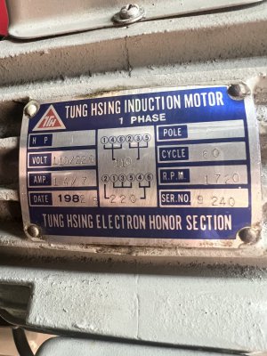
I have a new to me, 1982 vintage Shen Wei 8x30 knee milling machine. It had a failing push button start switch (mechanical, not magnetic) and was wired to run on 240 VAC single phase. It has no option for anything other than on/off on the electrical side of the equation. It had a step pulley system to handle the mechanical half of that equation. The motor is most likely original to the machine as the data plate has a manufacture date of 9/1982 stamped on it and the machine itself (data plate on the main casting) has a date of 1982.
The motor data plate:
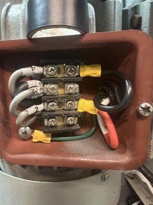
Internal wiring for the motor:

The wiring is consistent with the motor data plate and the unit was operational when I bought it. It ran excellent with no known issues at the time I bought it. When disassembling the machine to move it, I found that the wires inside of the machine were not up to any level of safe with poorly sized wire nuts and failing insulation on what quite frankly looked like scrap house wire. Now, this is not to say that it may have been factory installed in Taiwan when the unit was produced, but I wanted to remedy the problem. I say this because running new wires is already in the equation and not a barrier And other than major components we have a blank slate.
As a note for the picture above, leads 1-4 are gray wires and leads 5 and 6 are black wires which appear to be the wires to the start capacitor. All of the internal wiring appears to be in good shape and the as yet untested capacitor passed a visual “doesn’t look bad” inspection.
Here is the real root of the question, can this motor be run in both directions? I have a lathe and mill and neither are running and I feel like I will never get to use them because the projects to get them running keeps growing and not shrinking. I know that a 3 phase motor and VFD is a very viable option and would almost be preferred because can add the potential of variable (within reason) speed to the machine. That coupled with the step pulleys of simplifying to a single pulley set up would be a luxury. My concern with this time, knowledge and as with everyone money. Time in that I don’t have a lot of extra time and would love to be able to use my new machine instead of shuffle parts around the garage and hope to get it running some day. Knowledge, the opening statement should be enough there. Of course money is always an issue. If I can use the motor I have, it will hit the sweet spot, get me running and learning so that I can maybe upgrade later.
Making any physical changes to the motor to achieve reverse, if possible, will be handled by a professional. Although I am sure it is easy and I could do it, it is 100% outside of my knowledge base at this given time.
To those that know more than me, which I guarantee is a lot of people: teach me, guide me, chastise me if necessary.
I have a new to me, 1982 vintage Shen Wei 8x30 knee milling machine. It had a failing push button start switch (mechanical, not magnetic) and was wired to run on 240 VAC single phase. It has no option for anything other than on/off on the electrical side of the equation. It had a step pulley system to handle the mechanical half of that equation. The motor is most likely original to the machine as the data plate has a manufacture date of 9/1982 stamped on it and the machine itself (data plate on the main casting) has a date of 1982.
The motor data plate:

Internal wiring for the motor:

The wiring is consistent with the motor data plate and the unit was operational when I bought it. It ran excellent with no known issues at the time I bought it. When disassembling the machine to move it, I found that the wires inside of the machine were not up to any level of safe with poorly sized wire nuts and failing insulation on what quite frankly looked like scrap house wire. Now, this is not to say that it may have been factory installed in Taiwan when the unit was produced, but I wanted to remedy the problem. I say this because running new wires is already in the equation and not a barrier And other than major components we have a blank slate.
As a note for the picture above, leads 1-4 are gray wires and leads 5 and 6 are black wires which appear to be the wires to the start capacitor. All of the internal wiring appears to be in good shape and the as yet untested capacitor passed a visual “doesn’t look bad” inspection.
Here is the real root of the question, can this motor be run in both directions? I have a lathe and mill and neither are running and I feel like I will never get to use them because the projects to get them running keeps growing and not shrinking. I know that a 3 phase motor and VFD is a very viable option and would almost be preferred because can add the potential of variable (within reason) speed to the machine. That coupled with the step pulleys of simplifying to a single pulley set up would be a luxury. My concern with this time, knowledge and as with everyone money. Time in that I don’t have a lot of extra time and would love to be able to use my new machine instead of shuffle parts around the garage and hope to get it running some day. Knowledge, the opening statement should be enough there. Of course money is always an issue. If I can use the motor I have, it will hit the sweet spot, get me running and learning so that I can maybe upgrade later.
Making any physical changes to the motor to achieve reverse, if possible, will be handled by a professional. Although I am sure it is easy and I could do it, it is 100% outside of my knowledge base at this given time.
To those that know more than me, which I guarantee is a lot of people: teach me, guide me, chastise me if necessary.


