-
Welcome back Guest! Did you know you can mentor other members here at H-M? If not, please check out our Relaunch of Hobby Machinist Mentoring Program!
You are using an out of date browser. It may not display this or other websites correctly.
You should upgrade or use an alternative browser.
You should upgrade or use an alternative browser.
Can you identify the pressure angle of this gear?
- Thread starter stioc
- Start date

- Joined
- Feb 13, 2017
- Messages
- 2,138
The 9X20 Grizzly lathes are/were G-4000 and G-1550. Spindle thread is biggest visible difference. One made in mainland China, the other in Taiwan. In either case, the gears are 20 deg, modulus 1. I have the 1550 and have used gears from a HF machine. They interacted fine.
Bill Hudson
@Bi11Hudson thanks for confirming that. I was comparing that gear with this silhouette and couldn't quite tell. Now I know which gear cutter set to buy if I decide to make some odd ball change gears for the lathe.

- Joined
- Feb 25, 2017
- Messages
- 58
@Bi11Hudson thanks for confirming that. I was comparing that gear with this silhouette and couldn't quite tell. Now I know which gear cutter set to buy if I decide to make some odd ball change gears for the lathe.
Whenever I need to answer this question & the gear has been large enough, I make a rubbing of the gear. Scan it & then import it as a sketch/whatever into the CAD program of your choosing, sketch a few lines over the gear & then measure.
Works pretty well.
Sent from my SM-G900V using Tapatalk
- Joined
- Jun 7, 2013
- Messages
- 10,086
Nearly all metric gears that one will encounter are 20 deg. pressure angle. If one works with gears often, they should buy a set of templates that come with both pressure angles on each template of a different pitch in all the common pitches. Also stock gear catalogs usually have a page with full size printed representations of all the common pitches.
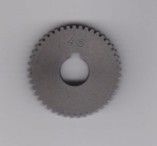
So I tried the scan and import method, I failed. The scan (on my flatbed scanner) comes out as a jpg. Tried converting it to SVG or DXF using online converters and then tried importing it into Fusion 360 but the conversion makes a very crude looking eclipse. Attached is the scanned gear if anyone's curious enough to want to give it a try.
Attachments
- Joined
- Feb 25, 2017
- Messages
- 58
Solidworks has an import photo option. You just place it onto a plane & then start a sketch on the same plane. I just draw some lines & curves (if I'm feeling adventurous) & then measure the angle. I've never actually tried to convert one into geometry.So I tried the scan and import method, I failed. The scan (on my flatbed scanner) comes out as a jpg. Tried converting it to SVG or DXF using online converters and then tried importing it into Fusion 360 but the conversion makes a very crude looking eclipse. Attached is the scanned gear if anyone's curious enough to want to give it a try.
Is there no similar option in fusion?
Your photo is exactly why I try to make a rubbing first if the gear size allows it.
Regards,
Steve
- Joined
- Jun 7, 2013
- Messages
- 10,086
I used my optical scanner on the picture; it is 20 degree P.A. ---
Thanks guys! Now you guys are making me feel dumb, what's a 'rubbing' and what's an 'optical scanner'? 
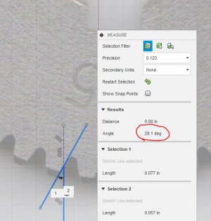
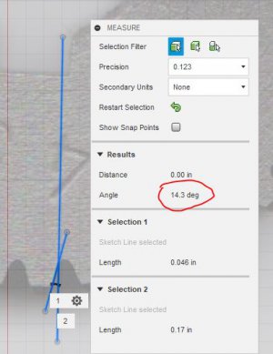
I'm trying to learn the technique for future use so I tried the lines on the jpg and I can make the angle whatever my brain leans towards lol See the two comparisons.
I'm trying to learn the technique for future use so I tried the lines on the jpg and I can make the angle whatever my brain leans towards lol See the two comparisons.