Centrifugal Start Switch and Drum Switch Retrofit

I don't want to have the hot left unswitched or switched with a separate switch... BUT that just means the rotary switch needs another pair of poles to handle the hot switching. It seems at first glance that a switch of that Brand with more poles IS an option, so I think you have found the answer to my crazy wiring by finding the brand of switch I need to buy,... Thanks for your help.

* BTW, I searched for replacement motors earlier today and almost every reversible motor that I saw had only 2 legs that needed to switch to change spin direction. The more I looked, the more I wondered what the difference is in the windings that makes my motor's directional switch so much more complex.

I just need to do a pin map on a piece of paper and verify that I'm getting all the legs taken care of and I'm almost finished with the changes.

* I made my Draw bar style chuck retainer for reverse rotation for around $30. I have to take a few pictures and post them and the parts list on my other thread.
 
The difference is some Dayton motors use stud 4 as a mechanical structure for the centrifugal switch making it difficult to separate the start leg from the main windings. You motor may be this way. Most likely it is.
I believe I helped a couple other members get around this limitation- let me check my notes. You may be able to use the switch you have after all
 
I already bought a 20 pole switch for $30. The switch in this thread can't be used for my motor. I either need a whole lot of poles or a more complex switch. If any 2 poles rely on a bus bar connection for part of their circuitry for one spin direction, and one of those paired wires has to change pole or change paired wires, the buss bar connection can't be switched so it is either always there or always removed... It actually reduces the number of switchable poles if you keep the buss connector and reduces the number of connections if you remove the buss bar.... too simple a switch for my crazy wiring

Thanks for your help
 
OK that's cool, I was going to say that I believe you can make a slight change to the motor terminals (outside) so that swapping only 2 wires will change the direction. It looks like Red and Stud 4 are the start leg.
I thought I'd go ahead and post it anyhow for the benefit of anyone else who might have the need- Sounds like you have it well in hand tho
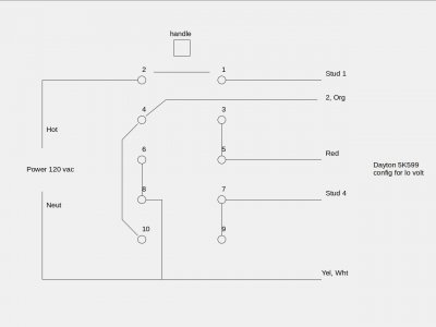
This is an educated guess but should work with Mike's original switch: (Yel, Wht, and Red are pulled off and extended)
Dayton5KchtUD.jpeg
 
Last edited:
OK that's cool, I was going to say that I believe you can make a slight change to the motor terminals (outside) so that swapping only 2 wires will change the direction. It looks like Red and Stud 4 are the start leg.
I thought I'd go ahead and post it anyhow for the benefit of anyone else who might have the need- Sounds like you have it well in hand tho
This is an educated guess but should work with Mike's original switch: (Yel, Wht, and Red are pulled off and extended)
View attachment 470917
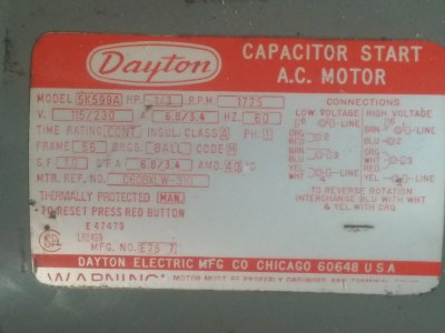
With all due respect,.....This will NOT work, you should take it down.... Yellow and white are together in one spin direction and split to different poles on the other spin direction in the manufacturer's wiring diagram. I posted a correct schematic (for a different switch) on the thread I started when it was obvious that this switch would NOT work for my motor's wiring.... Taking it down might prevent someone from burning up their motor by wiring this model incorrectly...
 
Theoretically this should work as it swaps the start leg rather than the two main windings- but I don't have the hardware here
to check it- like I said it was an educated guess
The difficulty with some of the Dayton motors is one of the power studs is mechanically one side of the start leg which makes it
tough to separate them- in this case the factory wants you to swap the main windings but if the start leg can be broken free then
only the red and the stud 4 need to swap
-M
 
Actually the red stays where it is and the orange moves according to the schematic,... here ya go, here's the schematic again.

20230918_130528.jpg
 
Last edited:
Back
Top