Centrifugal Start Switch and Drum Switch Retrofit

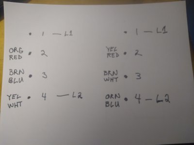
Now that the testing is completed, I'll purchase a nice piece of wire and a plug so I can do the final wiring.

Later this week, I'll start a thread of my conversion here in case anyone else needs to covert to single phase.
Thank you for joining us, how about some pictures? Some of the machine would be nice, but I'm interested in the car......:)
Good morning Aukai, my avatar is an image of a 67 Shelby GT 350 that looks like the Shelby I once owned which sadly I sold back in the mid 1990's. I don't want to highjack this thread, so I'll share some photos with you on your page.
 
The Pin out drawing has a mistake on page one. On the center lever position drawing there's a missing buss bar in the drawing between the 3rd and 4th terminals on the lookers left side

The reason I bring it up is I have this same cheapo switch and am pursuing a configuration that will allow me to reverse my lathe's spin direction also. From what I can tell, this switch can NOT do the job of switching my motor. Wires that have to be split from sharing a terminal connection and then paired with a different wire on a different terminal can't be on terminals that have buss bars because those connections need to be switched off when the spin direction lever is switched to go the other way... If someone can show me that I'm wrong that would be awesome, but this is the second time I've sat down with a copy of the pinned connections and I seem to need more terminals... Here's my info with the updated pin drawing.

I'm sticking with the 120V wiring because the lathe is small
 

Attachments

  • 20231212_124715.jpg
    20231212_124715.jpg
    128.8 KB · Views: 14
  • 20230918_130528.jpg
    20230918_130528.jpg
    293.6 KB · Views: 14
  • drum switch map1.jpg
    drum switch map1.jpg
    142.2 KB · Views: 5
The Pin out drawing has a mistake on page one. On the center lever position drawing there's a missing buss bar in the drawing between the 3rd and 4th terminals on the lookers left side

The reason I bring it up is I have this same cheapo switch and am pursuing a configuration that will allow me to reverse my lathe's spin direction also. From what I can tell, this switch can NOT do the job of switching my motor. Wires that have to be split from sharing a terminal connection and then paired with a different wire on a different terminal can't be on terminals that have buss bars because those connections need to be switched off when the spin direction lever is switched to go the other way... If someone can show me that I'm wrong that would be awesome, but this is the second time I've sat down with a copy of the pinned connections and I seem to need more terminals... Here's my info with the updated pin drawing.

I'm sticking with the 120V wiring because the lathe is small
i assure you no mistakes were made on my part, my motor runs as intended

if you are trying to wire your switch like i did, you will not get it to work.

i have installed a sinpak switch.

unless you have a sinpak switch- the wiring diagram will not be useful to you
 
Last edited:
Your pin drawing is missing the buss bar in the center position drawing...... You have that buss bar connection drawn correctly in the F and the R drawings. I just assume that you just left the connection out accidentally in the center drawing.

Basically, I made my own pin drawing from yours so I could work out my wiring issue since I'm using the same switch. Then I went and checked the drawing with the switch to make sure I had drawn it correctly and noticed the missing connection in the C drawing. If I'm wrong, I apologize for seeming like a dick.

I'm pretty sure this switch can't change the spin direction on my motor given the winding requirement on the motor's ID plate. Yes, I know it's different than yours which uses a sinpak


markba633csi asked me to post my wiring issue in my other thread, and I posted it here because I saw your video in my google search and followed it back here. I thought if I got you to see my wiring diagram you would either tell me that the switch I have can't do the job as I suspect or tell me how to do it...​

what do ya think?​

Doctors Drum Switch1.jpg

 
If that Dayton motor is the one you want to use- congrats, that's officially the weirdest one I have come across yet.
Not unusual for Dayton.
Looks like they want you to swap two pairs to reverse it. Probably the run windings. It also looks like the red and the brown maybe are the start leg. But if they are then why do they make you swap 2 pairs? Don't know
So I would try swapping those two first and see if it reverses it without causing some other problem or tripping the breaker
This motor may not be configurable with that drum switch- you may have to get one with more poles- per Llewelyn Moss
 
Last edited:
Thanks for responding..... I have done a fair bit of electrical work over the years so I'm not clueless by any means. I built my three phase converter myself with some help from the internet. When I first looked at this motor and the instructions on the face plate, I compared what needed to be done to it with some of my googled results from various other motors I found and thought exactly what you said.... "Weird!" but, that's the wiring on the motor that I have, so I wanted to investigate the possibility of using it.

This motor came with the lathe when I bought it. I'm not married to it, and when I saw the info plate I knew it was going to be a headache, but I wasn't sure if it was impossible with this switch but I suspected this switch could not be configured for both spin direction schematics as shown.

I don't need reverse spin for some pressing project at the moment, but I want it in the future so I can make faster light final passes when threading aluminum for better thread quality by using with an upside down cutter moving away from the headstock which is a lesser risk of a crash cutting at that higher speed.

I'll check out your suggestion and get back to you. I'm thinking about a different switch with 3 lines of 5 poles instead of the 2 lines of poles. This way the center line of poles could contain the 3 pole connections and it could be distributed to one set of wires in one direction and the other configuration in the other. Unused poles on either side would be isolated by not having any buss bars, so each direction's connections have no backfeed from connections on the other side. when those connections are supposed to be off......
 
Yep, you just need more poles. I'm guessing just swapping the red and brown won't work. Couldn't be that easy
 
Thanks for responding..... I have done a fair bit of electrical work over the years so I'm not clueless by any means. I built my three phase converter myself with some help from the internet. When I first looked at this motor and the instructions on the face plate, I compared what needed to be done to it with some of my googled results from various other motors I found and thought exactly what you said.... "Weird!" but, that's the wiring on the motor that I have, so I wanted to investigate the possibility of using it.

This motor came with the lathe when I bought it. I'm not married to it, and when I saw the info plate I knew it was going to be a headache, but I wasn't sure if it was impossible with this switch but I suspected this switch could not be configured for both spin direction schematics as shown.

I don't need reverse spin for some pressing project at the moment, but I want it in the future so I can make faster light final passes when threading aluminum for better thread quality by using with an upside down cutter moving away from the headstock which is a lesser risk of a crash cutting at that higher speed.

I'll check out your suggestion and get back to you. I'm thinking about a different switch with 3 lines of 5 poles instead of the 2 lines of poles. This way the center line of poles could contain the 3 pole connections and it could be distributed to one set of wires in one direction and the other configuration in the other. Unused poles on either side would be isolated by not having any buss bars, so each direction's connections have no backfeed from connections on the other side. when those connections are supposed to be off......
You find motors with thermal protection (manual or automatic) can be pain to wire .
They also pain trying how too via posting. I just did new motor for mill last year using a standard drum switch.

Dave
 
I would try the following test: With motor configured for Low Volt, pull off the yellow and white wires from stud 4 with power applied to
stud 1 and 4. If the motor is cold- no current flow- then a 4 pole double throw 3 position switch (16 terminal) could be used. Only if the start leg
is not connected to stud 4- but it could be. Good ol' Dayton- always full of surprises
On Amazon there are "Baomain" brand switches of that type for around 12 bucks.
Example: (this would not work if there are any hidden connections to stud 4 behind the terminal board- would require a 5 pole switch or separate on/off switch in series with the hot line)
Dayton5k599dr.jpeg
 
Last edited:
Back
Top