This is my first thread here, I think I have it in the correct forum but please move it if I've erred!
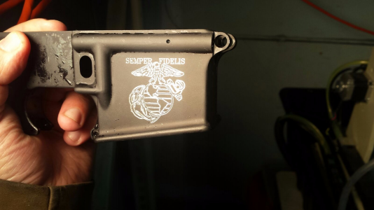
A few years ago I purchased one of the common 6040 desktop milling machines from Ebay. Despite differing brand names and Ebay sellers I think there's just one or two factories in China that crank these things out. I was aware (or thought I was) of the limitations of these machines: Small working area, low rigidity, and overall cheap build quality. My purpose for this machine was simply as an engraver, primarily in aluminum, to make decorative engravings on firearms and other small items as need be. Engraving doesn't involve tremendous cutting forces, and positioning accuracy isn't critical due to the decorative nature of the work. I encountered a slew of problems but trucked on through them to press the 6040 into service. I'm in a slow period at the moment where the 6040 isn't being used and I can take it offline and try to improve it. If anybody is considering one of these desktop mills, I would advise against them. For the time and money I have in it I would have been better off selecting a higher quality machine from the start.
The most immediate problem I encountered was connecting the control box to a computer. The connection is to be made by parallel port, which is a rare feature on modern computers. To run this machine I purchased a refurbished business surplus workstation that came with windows XP. This was important because Mach 3 only has parallel port drivers for 32 bit systems and if I recall correctly XP was the last supported operating system. The computer didn't come with a parallel port so I bought a card to put in a PCI slot. The first control box I tried would not communicate with the PC no matter what I tried. I read that one solution was to use a Smoothstepper motion control board so I ordered one. As it was shipping I tried a different control box (a shipping mishap left me with three of them - long story) and I was able to get motion. I decided to keep the Smoothstepper anyhow because it was highly spoken of, so the new connection went by ethernet cable to the Smoothstepper, then via parallel port to the functional control box.
I then had difficulty controlling the motion due to incorrect pinout settings in the software. The manual was poorly written and of no help, but I muddled through with trial and error. I still do not have optimized profiles for the steppers but what I have worked and I needed the 6040 to be running so good enough. Mach3 was giving me many other issues as well, and in talking with their customer support I discovered that the copy of Mach3 included with the 6040 was pirated. After ridding myself of the pirated version and installing a legitimate copy most of my problems disappeared, although the stepper settings are still iffy and I need to optimize them.
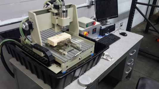
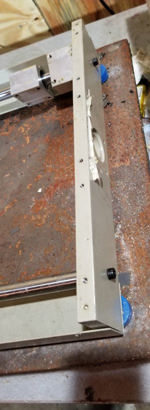
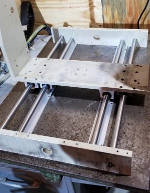
Another problem that immediately presented itself was the nature of the machine's bed. Poor quality aluminum extrusions meant there was no way to tram the spindle to the bed due to uneven and erratic warping. To fix this problem I purchased an aluminum tooling plate, drilled and tapped holes on my Bridgeport, and mounted it in its place. This greatly increased the usefulness of the 6040 by increasing rigidity and allowing me to tram the spindle.
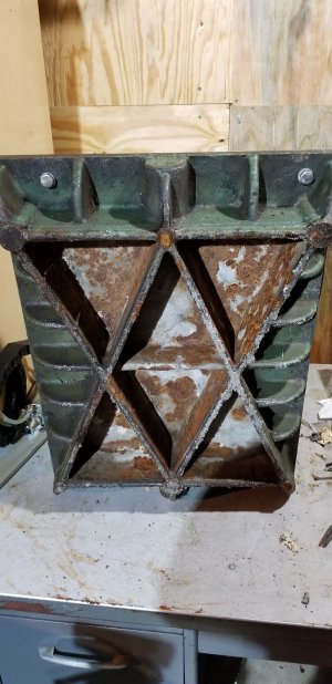
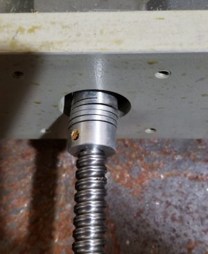
The leveling feet of the 6040 had been damaged in transit, and after having already had one lengthy battle with the Chinese seller I didn't attempt to get replacements sent out. Instead, I purchased a scrap cast iron surface plate and drilled through holes to mount the 6040. Here I believe I made a mistake: In an effort to damp vibrations, I put plastic vibration damping pads between the machine frame and the base, mounted on the bolts I used to join the two. In hindsight that seems to me counterproductive: The mass of the surface plate (I haven't weighed it but I can barely lift it by myself and I'm a big guy) and the properties of its cast iron provide plenty of vibration damping, and the gap between the 6040 frame and the surface plate/bed allowed for flexing and didn't take advantage of the rigidity the surface place could have provided.
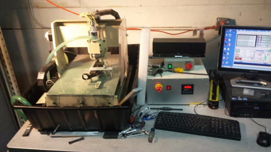
I dropped the whole kit and caboodle into a concrete mixing tub, filled a bucket with coolant and a fountain pump, and it was good enough to press into service. I was getting acceptable results although the machine ran very slowly. It filled my business need and so I left it alone.
After being in use for a couple years I noticed a drastic decrease in the quality of engravings it was outputting. Worryingly, the 6040 seemed to be less rigid and I could flex the machine dramatically by applying pressure to the spindle with my hand. Since my need for engravings has tapered off I've decided to investigate what's going on and see what I can do to turn this into a decent little milling machine. I have several CNC conversions planned and no machine building experience so this is a good first project.
A few years ago I purchased one of the common 6040 desktop milling machines from Ebay. Despite differing brand names and Ebay sellers I think there's just one or two factories in China that crank these things out. I was aware (or thought I was) of the limitations of these machines: Small working area, low rigidity, and overall cheap build quality. My purpose for this machine was simply as an engraver, primarily in aluminum, to make decorative engravings on firearms and other small items as need be. Engraving doesn't involve tremendous cutting forces, and positioning accuracy isn't critical due to the decorative nature of the work. I encountered a slew of problems but trucked on through them to press the 6040 into service. I'm in a slow period at the moment where the 6040 isn't being used and I can take it offline and try to improve it. If anybody is considering one of these desktop mills, I would advise against them. For the time and money I have in it I would have been better off selecting a higher quality machine from the start.
The most immediate problem I encountered was connecting the control box to a computer. The connection is to be made by parallel port, which is a rare feature on modern computers. To run this machine I purchased a refurbished business surplus workstation that came with windows XP. This was important because Mach 3 only has parallel port drivers for 32 bit systems and if I recall correctly XP was the last supported operating system. The computer didn't come with a parallel port so I bought a card to put in a PCI slot. The first control box I tried would not communicate with the PC no matter what I tried. I read that one solution was to use a Smoothstepper motion control board so I ordered one. As it was shipping I tried a different control box (a shipping mishap left me with three of them - long story) and I was able to get motion. I decided to keep the Smoothstepper anyhow because it was highly spoken of, so the new connection went by ethernet cable to the Smoothstepper, then via parallel port to the functional control box.
I then had difficulty controlling the motion due to incorrect pinout settings in the software. The manual was poorly written and of no help, but I muddled through with trial and error. I still do not have optimized profiles for the steppers but what I have worked and I needed the 6040 to be running so good enough. Mach3 was giving me many other issues as well, and in talking with their customer support I discovered that the copy of Mach3 included with the 6040 was pirated. After ridding myself of the pirated version and installing a legitimate copy most of my problems disappeared, although the stepper settings are still iffy and I need to optimize them.
Another problem that immediately presented itself was the nature of the machine's bed. Poor quality aluminum extrusions meant there was no way to tram the spindle to the bed due to uneven and erratic warping. To fix this problem I purchased an aluminum tooling plate, drilled and tapped holes on my Bridgeport, and mounted it in its place. This greatly increased the usefulness of the 6040 by increasing rigidity and allowing me to tram the spindle.
The leveling feet of the 6040 had been damaged in transit, and after having already had one lengthy battle with the Chinese seller I didn't attempt to get replacements sent out. Instead, I purchased a scrap cast iron surface plate and drilled through holes to mount the 6040. Here I believe I made a mistake: In an effort to damp vibrations, I put plastic vibration damping pads between the machine frame and the base, mounted on the bolts I used to join the two. In hindsight that seems to me counterproductive: The mass of the surface plate (I haven't weighed it but I can barely lift it by myself and I'm a big guy) and the properties of its cast iron provide plenty of vibration damping, and the gap between the 6040 frame and the surface plate/bed allowed for flexing and didn't take advantage of the rigidity the surface place could have provided.
I dropped the whole kit and caboodle into a concrete mixing tub, filled a bucket with coolant and a fountain pump, and it was good enough to press into service. I was getting acceptable results although the machine ran very slowly. It filled my business need and so I left it alone.
After being in use for a couple years I noticed a drastic decrease in the quality of engravings it was outputting. Worryingly, the 6040 seemed to be less rigid and I could flex the machine dramatically by applying pressure to the spindle with my hand. Since my need for engravings has tapered off I've decided to investigate what's going on and see what I can do to turn this into a decent little milling machine. I have several CNC conversions planned and no machine building experience so this is a good first project.

 .
.