Andy - Just finished reading this great thread.
Man that was a lot of work. Hope you did not pay to much for the lathe.
It seems like every thing is a project but you tell yourself while you are in there might go head and do just once.
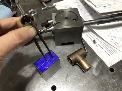
You inspired me to think about hand scraping my crossfeed and compound dovetails.
I am reconditioning my 1946 Clausing 100 mk3 lathe and upgrading to a quick change gear box and the advance apron.
My thread is under the Clausing section.
To save some time, you should check out this site:
To place an order please email: info@bmpartstech.com
bmpartstech.com
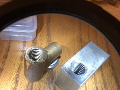
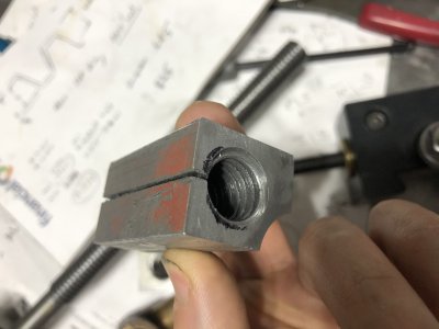
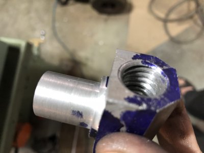
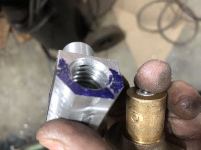
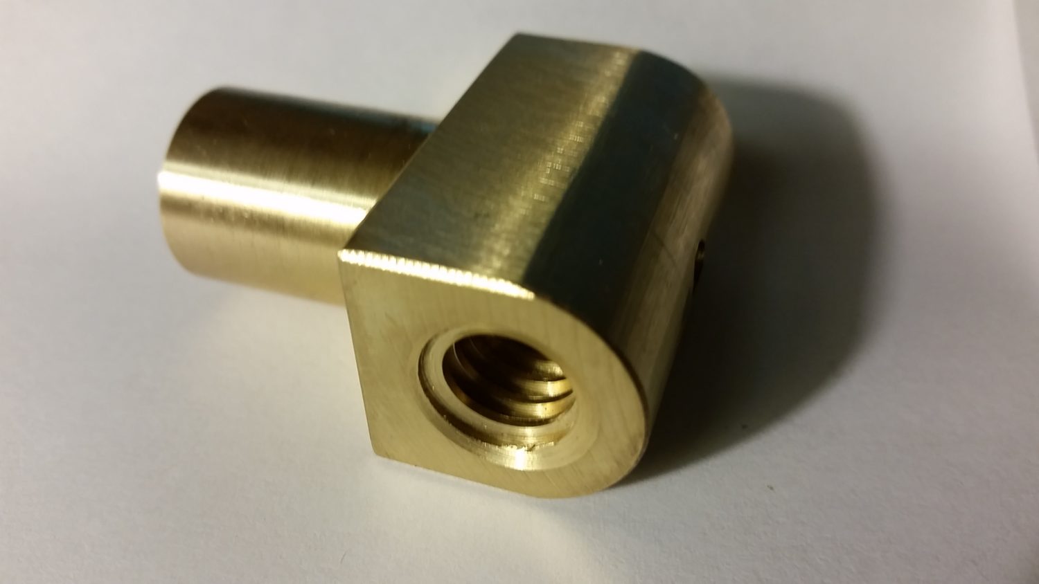
Clausing Lathe Cross Feed Nut - Cross feed Nut for 5900 Series lathes.
3/4″ diameter shank, 5/8″-10 Left Hand ACME Threads
– please measure your screw before ordering to confirm it is correct for your machine.
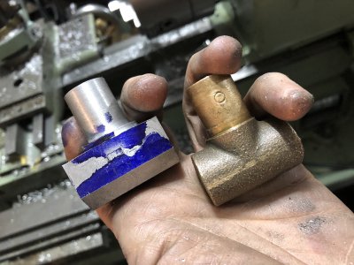
Made from 360 Brass. $55
I have replace both the crossfeed and compound lead screw nuts from them. The fit was right on.
If you are in Indianapolis, Indiana- they only have one machine shop? Would think with all the manufacturing going there would be more. My wife has family down in Columbus/Hope of Indiana - always looking forward for a trip up there.
Bob G.