I have posted this on other sites so my apologies if you have seen it before but this is the first site I have run across specific to Clausing.
Following is a description of some tips and improvements for tramming a Clausing 8520 mill. This may work for other similar ones like grizzly G0696 round ram head mil or perhaps A1S mill-Drill units like HF 40939.
I found it most important to have the clamp bolts as tight as possible when adjusting the head, this reduces movement when it is finally clamped tight. I chucked up a drill rod and adjusted the clamping bolts (one at a time) to the point where I could just barely tilt it by hand then marked the bolts. At this point I found I could move the head with a long wood stick, prying the extended quill or motor mount against the mill column. This seemed a little more repeatable than tapping on the head with a plastic mallet.
There are lots of recommendations on the web for how to measure Tram, I used a DTI held in a collet and rotated the quill between 2 different 123 blocks. Start with the indicator just barely contacting the lower block, carefully rotate to the other block and move the head so the needle moves 1/2 way back to zero. It only took a couple of iterations to get the same reading on both blocks. I find it works best to tighten up the back clamp bolt first, then front. The DTI does still move a little as the clamp bolt is tightened so there might be some trial and error.
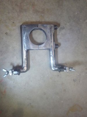
I decided to make a fine adjustment attachment for the mill. After a couple of quick calculations, I started with 1.125 shaft (actually annealed torsion spring from an old Astro van) and 2 ea 0.25" thick plates. I welded together then bored the 2.995 holes to fit the mill ram shaft. This took awhile, probably would have been quicker to grind a treepanning bit? I have used hole saws but they are pretty slow also. Even cutting
out most of the metal with a cutout wheel or torch might of been faster.

Next I welded on the other parts and fit a couple of 10-32 adjusting screws and sawed the assembly in half vertically. Probably should paint it but can't wait to try it out.

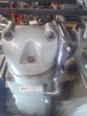
A little adjustment and it fits on the mill perfectly

The opposing adjustment screws made it very easy to adjust the tram. The adjustment screws are 6 in below the ram and offset from the center of the vertical bars by 2 inches. The thumb screws snug up but do not flex the assembly too much. If both screws are left snug there is little change in the tram as the ram clamp bolts are tightened. The entire tramming process took about 5 minutes not including photographs.
The entire assembly can be loosened and moved with one nut on the top (same nuts used in the mill table clamping kit). It can be easily removed or moved to the front of the column if more ram adjustment is needed.
There are a couple other things that can be checked. The above tram checks that the spindle is perpendicular to the table surface in one direction, it can also be checked front to back (nodding) but there is no easy adjustment on this mill (short of shimming or scraping).
The parallelism between the table top and bottom dovetails can next be checked by setting the indicator on the table (or a parallel block) and cranking the table in X and Y.
Deflection of the mill under load can be checked by using a fly cutter or large face mill and fine adjusting tram by trial and error to get the desired cross hatch pattern. If the pattern changes depending on cutting load or direction it suggests some deflection in the machine frame or spindle.
For years I have gone to every contortion possible to avoid changing the head because it was such a pain to get it trammed back in. I wish I had made something like this long ago. This tool only works when the overarm is reasonably parallel to the Y axis so if I need to rotate the top of the column I will set the overarm length and tram first, slide the adjustment tool off then rotate the top of the column. I kind of like the idea it does not require any modifications to the mill itself.
I am sure many others have done something similar but a search did not find any, (probably a good indication of my poor search skills) so I figured I would share.


