Clausing 8520 TouchDRO

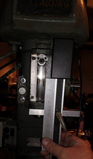
Well, I made a Z stop with larger threads (sort of) and I got the flat spot on the bottom of the head, drilled and tapped and added a bracket. Holding the new igaging scale up, there isn't enough room for the full 3" of z travel without also modifying the top cover. The igaging reader is tool tall.

Very sad. I really do not want to modify the top cover as I'd like to keep it original.

Also, maybe this is too much around the bottom of the quill. Could be in the way of installing collets, gages and no telling what. Second guessing the whole install now.

I have it on all the other axis with TouchDRO. I may hold off for now or modify a cheap caliper like I did on the Round Column mill.

Very sad.

Anyone have any thoughts or suggestions?
 

Attachments

  • Not Enough Height.jpg
    Not Enough Height.jpg
    46.2 KB · Views: 26
I did one a little different awhile back. Its a head that is similar to a caliper. I removed the quill stop and made a new one that left a lot more space for screws for attaching a piece of sheet metal that holds the head. If I remember correctly I had to remove the top pulley but not the spindle. I also had to machine a pocket into the pulley guard for the sliding head of the DRO. The scale is attached to the bottom with a clamp. I made a flat spot on the bottom of the mill head by mounting an angle grinder in the vise then running the table back and forth. Then I mounted a right angle drill in the vise to drill the 2 holes in the bottom. It has worked well for years.

This mill has never had a working brake, I just let it coast to a stop and grab the belt when I need to replace a tool in the spindle.

View attachment 392823


View attachment 392822
The brake is not to slow it to stop it.
it's only there for locking up while changing the endmills.
 
Nice job on the Z stop, looks very similar to what I did except mine is squared off at the top. Were you able to remove the adjustment screw from the bottom?

Not sure if It was clear from my photos but with the bottom clamp I made, nothing really sticks below the bottom of the spindle housing so I have never found it to be in the way of any operation. I did have to cut a hole in the belt cover, then I added some aluminum in there so the DRO head and bar would be protected in case the belt ever came off the bottom of the pulley. I use this DRO almost every time I use the mill. I was also a little nervous about cutting into the cover but have never regretted it. You do need proper lighting to be able to see the DRO easily, I found small "sewing machine light" on amazon, it is 110V LED with magnet base was cheep and works well.
I think the spindle DRO is a little more accurate than a Z axis on the table because the table always moves a little in Z and Y when it is clamped in place.

I think I could repair and reinstall a brake on my mill but it seems to get further and further down the list. I guess it makes sense to not use the spindle brake to slow down the mill, that would probably wear things out quickly. Just grabbing ahold of the 2 belts with one hand has worked fine for me.
 
z stop is very ugly. On a round column mill, you always have to plan on how much working height you need in the Z direction. So my spindle is either over extended or too short for a tool change. (the reason for the nice little knee mill) Found I did not tighten the drawbar for one of the center drilling operations and the hole was miss placed. Grrr. Also my stock is only 1" OD. 1.25 would be much better. Broke a tap in the first one and could not extract as the hole is partially in the .6875 OD of the quill stop. But, the second one is always faster to make. Needs a flat spot on the top though. I wanted to post some pics of it, but it is just atrocious. It's way uglier from the other side.

I see the clamp isn't in the way of the work, it's more of a visual thing being able to see what I'm doing. The bracket as shown is over length, as I haven't' determined how to short to make it, so it's a bit misleading. It's just with the reader being so long, it limits travel. I'm at a good point to pause and can continue later without tearing the machine down. Still thinking on it. Just hate to put a hole in the cover. So far I can take all this stuff off and get it back to stock. A few tapped holes never hurt anything. Some larger holes? They worry me is all.

I did not drill out below the adjustment screw. I still think it's a good idea, but will take more disassembly, setting it up in the other mill, longer drill bit (which I don't have) and making another fully threaded part. Maybe will do this later. If you ever need to access the quill stop, that pulley on the top has to be pulled off the bearings which I find ridiculous. The Z stop was lose on mine when I got it. I'll loctite it all when it goes back together. But if it loosens again, it comes apart. Allowing for easier removal would be just awesome and with the removable bracket under, it'd be very easy.

My brake is in 2 pieces. I may try making one out of something besides ductile cast iron (clausing spec). The pulley is expensive and long winded to make so I'd rather not damage it by putting something under it of the wrong material as the brake grabbs the ID of the pulley when you twist the brake lever. If you only use it once the mill has finished turning, maybe there is no issue. It'd be nice to have, although with a push pull drawbar and the small time I've had the mill, I've not really needed a brake. Although you do not know to miss what you've never had.
 
Have found a Wixey Drill Press Depth Gauge. Looks like the head may be small enough to fit. Anyone have one and can get some dimensions of the reader? Can't find that sort of detail online

I only see them for wood tools though.
 
Thought about this all day while at work. There is room under the upper pulley and over the cover. It may be pretty easy to make an adapter that just raises the cover giving room for the igaging reader and scale. Since I do not have a brake, I can get away with this. If you have a functioning brake, this may not work. Depending on how far up it needs to move, maybe just make a new shorter cam that operates the brake. Never give up.
 

Attachments

  • Room In the Housing.jpg
    Room In the Housing.jpg
    122.7 KB · Views: 13
Finally got the cover raised up. Made some brackets that both hold in the original holes as well as clamp to the head. Raised it up enough to get the reader in there. Only lost about .03 of vertical. Not too bad. And I can put it back stock.

I still need to make a bracket to attach the reader. The Brass I had laying around isn't quite up to the task.

Remember I have no brake, so I can raise the cover.
IMG_20220305_194250535_HDR.jpg
 
Was having lots of noise and my Z axis was climbing.

The scale was turned around in the reader and the ground contact in the reader was not making reliable contact.

If you look at the edges, one is smooth and the other textured from the finish on the aluminum. The smooth one is the ground contact.

Opened it up to check the solder joint and do a continuity check. Turned the scale around and all is good.

Recommendations on the site are good ones as I figured they were.
 
nice job, if I had thought about raising the cover I would if probably of done it that way instead of cutting a hole in the cover
 
There are many ways to skin the cat. You look around long enough and can find inspiration.

I took the cover off, put the 4 mounting screws back in and then sat the cover on top of those threads and noticed I had about all the height I needed. I was just trying to visualize where there was room and where there was not.

There was some light sanding and Dremel work, but no holes or openings were created.

They are nice old machines.. the more stock we can keep them the longer they will live.
 
Back
Top