That looks mighty fine! Have you calibrated your scales yet? I remember reading something about the W needing to be done separately but no info how to do that. I decided to just plug it into x and figure the correct counts. If I may ask, what are you using for a tablet mount?
-
Welcome back Guest! Did you know you can mentor other members here at H-M? If not, please check out our Relaunch of Hobby Machinist Mentoring Program!
You are using an out of date browser. It may not display this or other websites correctly.
You should upgrade or use an alternative browser.
You should upgrade or use an alternative browser.
Clausing 8520 TouchDRO
- Thread starter Briney Eye
- Start date
- Joined
- Jun 16, 2016
- Messages
- 221
I figure this ought to work:
1. mount a test indicator in the spindle
2. extend the quill fully and lock it
3. lay a 1-2-3 block flat on the table to provide a good reference surface (or just use a good spot on the table)
4. zero the test indicator on the top of the 1-2-3 block using the knee, and lock the knee
5. zero the DRO Z axis
6. stand a second 1-2-3 block on top of the first one
7. unlock the quill, zero the test indicator on the top of the second block, and re-lock the quill
8. scale the W axis CPI so the DRO says 3.000 inches (I suppose I should measure the block and use that number)
9. remove the standing 1-2-3 block
10. unlock the knee and crank it up to zero the test indicator on the flat 1-2-3 block
11. set the Z axis CPI so the DRO reads 0.000
The articulated arm is a CAMVATE camera mount, and the tablet holder is an ASICS.
Sounds like a plan to me. Thank you for the info on the tablet mount. It might sound silly but I have been putting my tablet on the mount I made for the lathe and having to look over at it which is not very handy or even possibly unsafe as I now think of it. Never thought of looking at camera gear.
- Joined
- Jun 16, 2016
- Messages
- 221
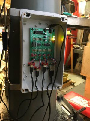
Mounted the Big Box O'Lectronics on the column today. I wound up switching to a normal USB connector for the W axis. There must be somebody online who carries cables with micro connectors on both ends, but I couldn't find them (Argh! Digi-Key has them, and I've been ordering from them for 30 years!).
The power consumption of the Mixed Scale board is so low I didn't bother with ventilation. It might get a little warm in there, but it won't get hot enough to be an issue. I simply notched the edge of the enclosure with a rat tail file for the cables:

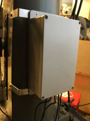
Buttoned up:

I just bent some 1/16" aluminum from the hardware store to make the brackets, and drilled and tapped the column for 10-24 button head screws.
The power consumption of the Mixed Scale board is so low I didn't bother with ventilation. It might get a little warm in there, but it won't get hot enough to be an issue. I simply notched the edge of the enclosure with a rat tail file for the cables:

Buttoned up:

I just bent some 1/16" aluminum from the hardware store to make the brackets, and drilled and tapped the column for 10-24 button head screws.
Last edited:
- Joined
- Sep 18, 2014
- Messages
- 8
Hi Jon, I watched your YouTube about this also. Your DRO installation looks great, Thank you for posting this. I am seriously thinking about using the same system on my 8520. I have a few questions.
1. What are your thoughts about the TouchDRO-bluetooth-to-tablet setup now that you've (presumably) had some time to use it?
2. Are you happy with the accuracy and consistency of the readout?
3. Any bugs or problems to report?
4. Does it ever lose the BT connection?
5. Are you fully satisfied with the Fire tablet for this application?
6. What length scales did you purchase for your X and Y? Did you cut them down to final length?
7. Did you maintain full travel of your table?
8. Anything else that you'd do differently if you did it again?
It looks like you installed everything so not to lose access to original locking handles or gib screws on the table and carriage, which is nice.
If I install this system I want to try to replace the USB cables from the reader heads with metal armored cable to make the installation more durable. Who knows, it might help with electro-magnetic shielding too.
Roger
- Joined
- Jun 16, 2016
- Messages
- 221
Hi Jon, I watched your YouTube about this also. Your DRO installation looks great, Thank you for posting this. I am seriously thinking about using the same system on my 8520. I have a few questions.
1. What are your thoughts about the TouchDRO-bluetooth-to-tablet setup now that you've (presumably) had some time to use it?
2. Are you happy with the accuracy and consistency of the readout?
3. Any bugs or problems to report?
4. Does it ever lose the BT connection?
5. Are you fully satisfied with the Fire tablet for this application?
6. What length scales did you purchase for your X and Y? Did you cut them down to final length?
7. Did you maintain full travel of your table?
8. Anything else that you'd do differently if you did it again?
It looks like you installed everything so not to lose access to original locking handles or gib screws on the table and carriage, which is nice.
If I install this system I want to try to replace the USB cables from the reader heads with metal armored cable to make the installation more durable. Who knows, it might help with electro-magnetic shielding too.
Roger
1. I've used it much more on the lathe at this point. Love it. Now that the holidays (and a family funeral) are past, I hope to get back on the mill and finish up some things there. I highly recommend adding decoupling capacitors in the read heads. I still haven't gotten to it on the mill, and it's flickering in the least-significant digit. On the lathe it didn't work at all without them.
2. Accuracy-wise, the aluminum scales are good enough for what I'm doing, and had maybe 0.001" of hysteresis when I checked with a test indicator.
3. No actual bugs, but I wish the Preference Banks could be named and were "smart" enough to remember which Bluetooth connection to use.
4. The connection on the lathe started out finicky. It was particular about which wall wart I powered it from. Luckily, I've saved a big box of them over the years. Adding the decoupling capacitors in the heads also seemed to make it more stable in that respect. It's rock solid now, and only loses the connection when we lose power. I used an old transformer-based supply for the mill, and it seems happy other than that last-digit flicker which I expect to go away when I add the decoupling.
5. The Fire works great. It just requires some finagling to get the Google Store installed on it first. PITA in that respect.
6. I cut the 4" stainless scale that I installed on the quill and the 24" aluminum scale for the X axis. As I say above, you will need carbide if you want to drill stainless scales, but a cutoff wheel in your Dremel will hack through it. Try not to get them too hot, since the scale is just glued to the beam. I could have left the X scale longer and shifted the mounting blocks out flush with the ends of the table and it might have looked a little better. I had a reason for making it shorter, but I can't remember what it was now. Old age
7. I have full travel on all four scales.
8. I keep wondering if I could have figured out a way to mount the X axis inside the table. I've seen it done with magnetic "tape" scales, where people have buried all of them inside the machine. You have to have a second mill to make the modifications, though. Other than that, it's made for a great setup.
-Jon
- Joined
- Sep 18, 2014
- Messages
- 8
Thanks for the information. Good to know about putting bypass caps in the reader head. Putting the x scale under the table is a neat trick for protecting it, but for me more work than I want to budget for the task.
- Joined
- Jun 16, 2016
- Messages
- 221
Thanks for the information. Good to know about putting bypass caps in the reader head. Putting the x scale under the table is a neat trick for protecting it, but for me more work than I want to budget for the task.
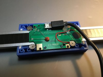
Here's a head with a 0.1uf ceramic decoupling cap installed between VDD and GND. I could have trimmed the leads a bit

- Joined
- Sep 18, 2014
- Messages
- 8
Leaving them long means they're still usable for something else if they don't work out there. I think I'll install them in preemptively, because once I get the scales aligned on the machine I won't want to take them off to make mods to the boards


