Clausing 8530 Restoration

Industrial Hygienist is another word for nerdy unicorn. Nah, I just have a couple of semesters studying the sorption exchange mechanisms in humic, fulvic, and tannic acids (environmental transport and fate). Those are the main components that retain pollution in peat wetlands. I took three additional classes on the ion exchange mechanisms in charged clays (some of the hardest I ever took- soil science, soil physics, hydrogeochemistry). Every one has industrial applications, now I can use the wetland chemical kinetics knowledge to model how a respirator cartridge sorbs a contaminant, and I can explain to the environmental scientists why they didn't find the chemical they spilled in the water (because it's in the soil and soil organic matter, for example). Utility engineers asked me to write the maintenance schedule for deodorizers at sewer lift stations because they were scared of the chemistry calcs (good thing, too). Nope, I'm just the handy guy they call who remembers his education and training and uses it to navigate complicated situations. I'm terrible at routine work, so I gravitate to the more complicated stuff. Then I turn around and remind people what they already know so they don't have to call me again, make them feel good about what they've done, then write a report to the command. It's one way to carve out a niche.
You know what they call someone who remembers their training………..smart!
 
I've reached a major milestone here folks, the lower end of the machine is all finished up.

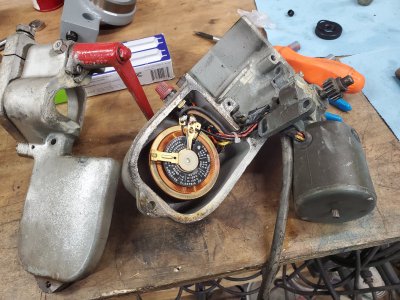
The power feed was the final piece to be restored on the lower end. I didn't get as many pictures of the assembly process but here's a few of before I took it apart.
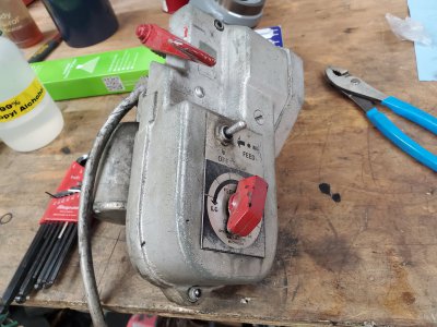
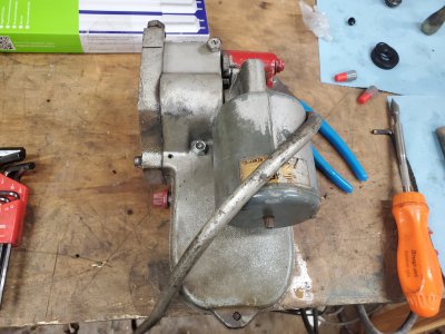
20230526_172834.jpg
20230526_172918.jpg
20230526_174148.jpg
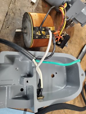
Some of the solder joints had to be undone to get everything apart, primarily the ones to the fuse. There was some insulation damage on the wire from the fuse to the variable transformer, so I removed both ends and replaced it.
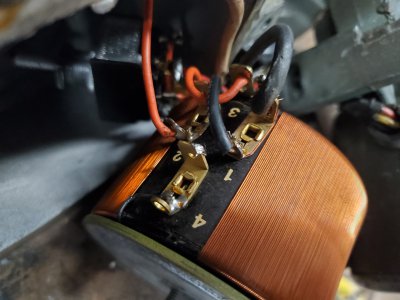
20230527_101500.jpg

I suspect some of the wiring at the switch was not original, but it seemed intact and serviceable, so I left it be.
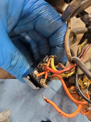
20230527_162947.jpg

I also replaced the power cord, sense the old one was showing some wear and covered in silver spray paint. All the connections that I touched were flux'd, soldered and covered in heat shrink.
20230529_140031.jpg

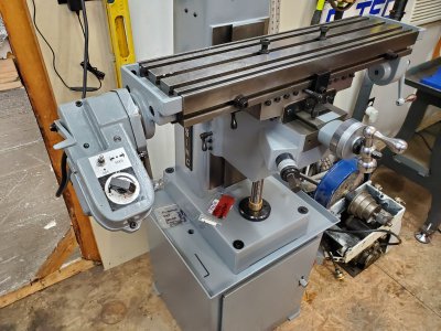
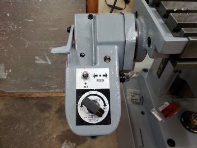
Here it is all finished up and installed. It took a bit of adjustment to get it all aligned and mesh up the gear in the power feed to the gear on the lead screw, but it wasn't too difficult to figure out.
20230601_170701.jpg
20230601_170708.jpg

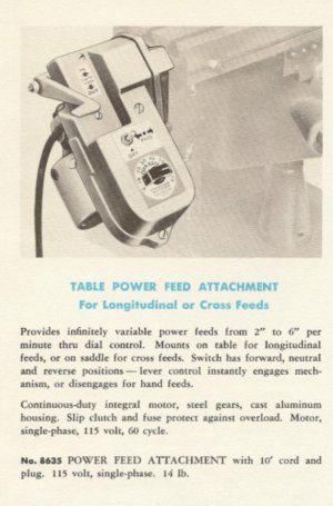
I found this clip of a brochure for the power feed, it mentions a clutch, but I'm not sure what they're referring to. Maybe one of you guys know what part is the clutch mechanism? Seems like the kind of thing I should tune to ensure it's functional. When I got it back together and started running the power feed I started thinking about what will happen when I crash the table into something and had thought maybe I'd be relying on popping the fuse. A clutch seems like a much better damage prevention feature, than waiting for the fuse to pop.
Screenshot_20230609_114040.jpg

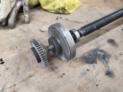
I'm thinking maybe the clutch they speak of is built into the gear assembly on the lead screw? I might try lossening the grip of those collars that clamp the gear in place. It's not obvious in this picture, but now that it's cleaned up, I can see there's a red fiber washer sandwiched in there with the gear.
20230517_140437.jpg
 
Last edited:
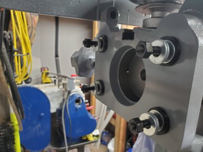
I started in on the motor, motor mount and idler pulley. I'm not sure I'll do anything with the motor as a friend of mine gave me a VFD that'll handle single phase input to 3ph output for a 1HP motor and another friend is giving me a 1hp 1750rpm 3ph 230v motor in 56c frame size. I'll need to fabricate a bracket to adapt the c-face mount motor to the foot style mount used on this machine. I've got it all designed in my head, should be pretty simple.

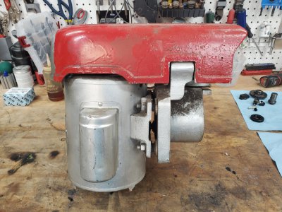
Here's the before pics.
20230528_095139.jpg
20230528_095149.jpg
20230528_095203.jpg

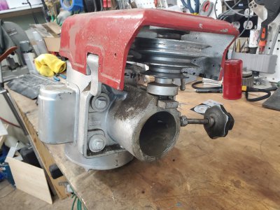
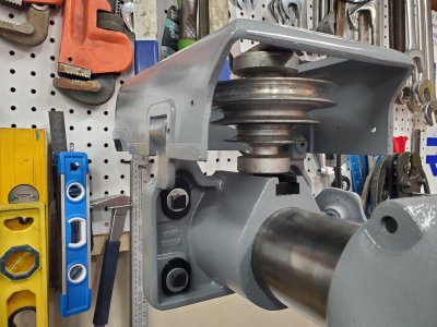
Image of the belt tensioning mechanism, mostly taken to assist in reassembly.
20230528_100133.jpg

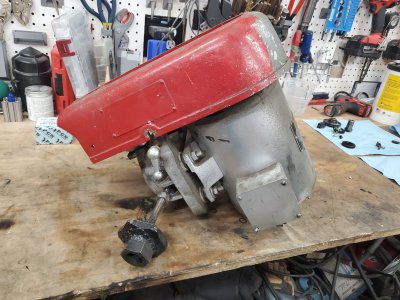
Hood latch mechanism details...
20230528_100214.jpg

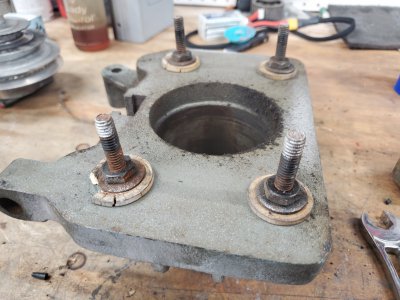
Motor mount dampeners are pretty rotten. I've designed new ones and am printing them out of a flexible TPU rubber material.
20230528_100732.jpg

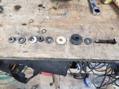
I like to have these stack up images, just incase I forget how things go back together and the exploded view/parts list isn't clear. This is for the motor mount, bolts, nuts, washers and dampeners.
20230528_100854.jpg

The last dampener was printed while I slept last night, so I'll get that installed this evening and get some pics of the finished motor mount.
 
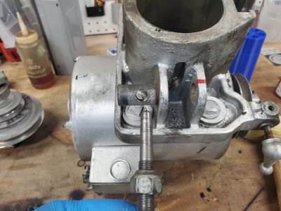
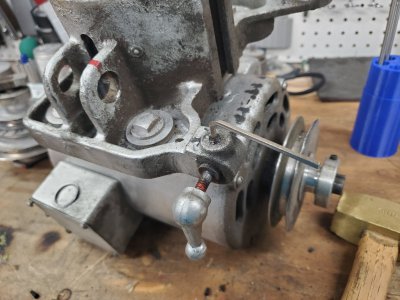
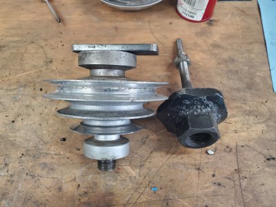
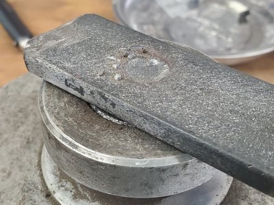
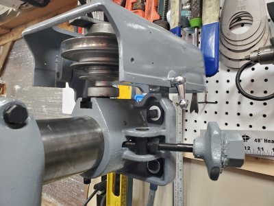
I've hit a bit of a snag with the idler pulley, the previous owner has chopped the shaft down and replaced the removable knob with a welded on piece of flat stock. No idea why this was done, possibly some kind of remediation of belt tension issues. You may have noticed he somehow welded (brazed?) a steel nut to the aluminum lock knob of the belt tensioning mechanism, I assume this was done to facilitate over tightening of the belts as well.

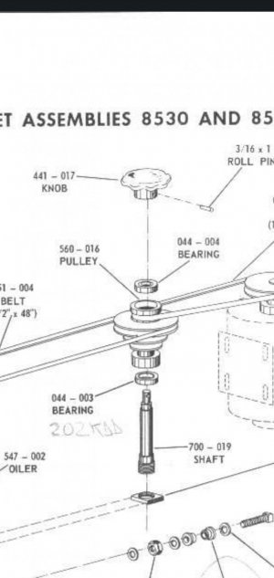
In order to replace the bearings on the idler, I'll need to dismantle the pulley, which is impossible with that bar welded on top. I called Clausing, they have the idler shaft and lock knob available but the price was something like $188 for the pair. Not a terrible price, I suppose. However, I do have a lathe and the raw material to fabricate a new one. Just a matter of skill at this point, never really made anything like this on the lathe, it would be my first attempt at threading. Then some sort of knob would need to be made, likely using my old mill/drill. The bearings are pretty rough in there, so I don't want to run it as is, at least not for long.

I suppose I should just jump feet first into it. Drill out those welds, disassemble, measure, turn new shaft, cut threads. Then fashion a knob (possibly just square) to be pinned on top. If I screw it up, then I just buy the replacements from Clausing.

Here's what I'm working with...
20230528_133533.jpg
20230528_133512.jpg

It should look more like this:

Screenshot_20230609-125210_Drive.jpg
 
Here it is all finished up and installed. It took a bit of adjustment to get it all aligned and mesh up the gear in the power feed to the gear on the lead screw, but it wasn't too dI found this clip of a brochure for the power feed, it mentions a clutch, but I'm not sure what they're referring to. Maybe one of you guys know what part is the clutch mechanism? Seems like the kind of thing I should tune to ensure it's functional. When I got it back together and started running the power feed I started thinking about what will happen when I crash the table into something and had thought maybe I'd be relying on popping the fuse. A clutch seems like a much better damage prevention feature, than waiting for the fuse to pop.

View attachment 450448

I'm thinking maybe the clutch they speak of is built into the gear assembly on the lead screw? I might try lossening the grip of those collars that clamp the gear in place. It's not obvious in this picture, but now that it's cleaned up, I can see there's a red fiber washer sandwiched in there with the gear.

I have an original manual, If you'd like to see it - let me know. It does talk about the clutch and it's adjustment. And I am in love with your resto work! It's really first rate. Thanks for sharing the internal pics of the power feed, folks seem to frown on them but I am sure glad I have it!
 
I have an original manual, If you'd like to see it - let me know. It does talk about the clutch and it's adjustment. And I am in love with your resto work! It's really first rate. Thanks for sharing the internal pics of the power feed, folks seem to frown on them but I am sure glad I have it!
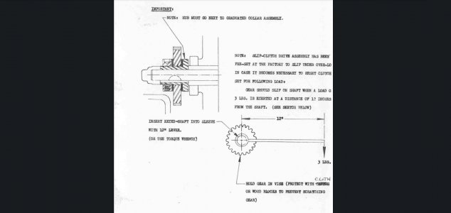
Thanks for the tip on the manual for the power feed. You're right, they have a calibration proceedure in there to set the slip of the clutch. As I suspected, the clutch mechanism is built into the gear that drives the lead screw. Looks like I need to clamp the gear in a vice and find a way to turn the hub with my torque wrench, then adjust so it slips at 3lb-ft.
Screenshot_20230610-070423_Drive.jpg

Sure would have been nice to have this manual before I torn the thing apart, not sure why I didn't think to look for it before. I need to remember to stop and have a look at the parts diagrams before taking things apart, there's been a few incidents that could have been avoided if I better understood what I was taking apart.
 
Here's the vibration dampeners I designed for the motor mount.
20230610_091334.jpg
20230610_091313.jpg
20230610_091305.jpg

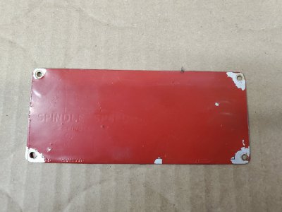
I still need to work out a way to get the red paint off of the spindle speeds nameplate. My experience so far with removing the red paint is that it's stuck on there much better than the silver paint. Obviously I'd like to preserve the text/images underneath the red paint. I chipped some off with my fingernail, so I may go at it with a plastic razor blade first to see if I can just scrape it off. Then maybe I move onto near boiling simple green extreme, my experience thus far is that it will strip the paint no problem, just not sure how much damage it will do to the ink or whatever was used on the plate originally.
20230610_091404.jpg
 
Looking great! Hey find out how to weld steel to an aluminum hand knob, will you?
I think that plate is gonna be a ***** to remove the red paint and preserve the underlying paint. You could order a replica? Someone here posted a resource. I wonder if thermal cycling could flake off the red?
 
Back
Top