Cleaning up a tired old carbide grinder

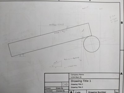
Been thinking about making the tilted holes. Have some ground angles that I can use to tilt the piece in the vise. From searching on HM I found @RJSakowski posted a picture of a fixture to find the virtual corner of a tilted piece. Was thinking about how to make this. More on how to fixture it for the weld so the tool will end up being useful. At the tilt angle, (15 degrees in my design) one needs to be able to touch off the dowel in the vertical plane. Is that sufficient? Don't quite yet understand this, enough. Need to noodle this some more.
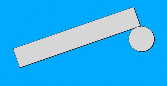
virtual_edge_finder.jpg
If I am visualizing this correctly, a dowel pin is placed on the welding table and a flat plate is placed over it. (Probably make it easier to clamp if there are two dowels) Then a weld can be made at the end of the plate joining the dowel. As long as the weld bead isn't too thick and the rod is still tangential to the plate surface one should be ok. Having not done "machining tolerance" welding before, how does one ensure the tangential condition is maintained when the weld cools? Assuming one welds only on the right side, won't the dowel try to rotate towards the contracting weld? Will it lift from the plate?
 
Been thinking about making the tilted holes. Have some ground angles that I can use to tilt the piece in the vise. From searching on HM I found @RJSakowski posted a picture of a fixture to find the virtual corner of a tilted piece. Was thinking about how to make this. More on how to fixture it for the weld so the tool will end up being useful. At the tilt angle, (15 degrees in my design) one needs to be able to touch off the dowel in the vertical plane. Is that sufficient? Don't quite yet understand this, enough. Need to noodle this some more.
View attachment 395053
If I am visualizing this correctly, a dowel pin is placed on the welding table and a flat plate is placed over it. (Probably make it easier to clamp if there are two dowels) Then a weld can be made at the end of the plate joining the dowel. As long as the weld bead isn't too thick and the rod is still tangential to the plate surface one should be ok. Having not done "machining tolerance" welding before, how does one ensure the tangential condition is maintained when the weld cools? Assuming one welds only on the right side, won't the dowel try to rotate towards the contracting weld? Will it lift from the plate?
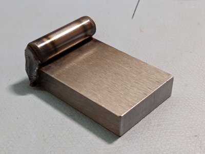
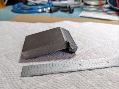
I made the plate the same width as the length of the dowel pin. I clamped the assembly vertically in a vise and welded the end, then flipped over and welded the other end. I then ground the end of the plate at around a 50º angle so that it was slightly below a tangent to the dowel pin. I had to do a little cleanup of the welds on the inside to allow a corner with an acute angle to fit properly.
 
I made the plate the same width as the length of the dowel pin. I clamped the assembly vertically in a vise and welded the end, then flipped over and welded the other end. I then ground the end of the plate at around a 50º angle so that it was slightly below a tangent to the dowel pin. I had to do a little cleanup of the welds on the inside to allow a corner with an acute angle to fit properly.
I do not understand this. Have to say geometry makes me struggle, so pardon my ignorance. Is the rod circumference tangent with the plate surface? (The plate surface which contacts the tilted work piece.) Is it necessary to touch off the top of the dowel to solve the geometry problem?

Assuming a workpiece with right angle corners, I have solved the horizontal placement of the workpiece corner, which I believe to be
D = measurement + 2*r + r*tan(theta)*cos(theta), where r is the radius of the dowel. Haven't yet solved for the Z part, but for me, since I am drilling through the part, not sure that it matters. If I had to partially drill through, I would solve for Z.

Perhaps we are trying to solve different problems with our fixtures?
 
Ok, I am solving a different problem from RJ. He was solving the level, but non-90 degree corner offset, and I am trying to locate hole offsets on a tilted 90 degree corner workpiece.

Once I know the reference point, given by REF = 2r + r tan(theta) cos(theta), (from above) then the new hole locations are s = xi cos(theta) away from the reference, where xi is the coordinate in the drawing in View001.
PXL_20220208_164938181.jpg
Now that I understand the basics, I will make this piece. Dowel on order, should be here tomorrow. Have some stock. Will grind off the top corner. In the drawing I was trying to solve the trig problem, not to make the piece easier to use.
 

Attachments

  • techdraw_mainblock.pdf
    211.1 KB · Views: 2
This didn't go as smoothly as I would have liked, but welded a dowel to a small plate to make the edge finder. Managed to weld it to the table. Oops. Need to grind it and clean up a ding or two. Tomorrow I should get an end mill with a longer LOC. That way I can true up the cast iron side a little easier. Then I can use this edge finder to locate the tilted holes.
PXL_20220211_030119362.jpg
 
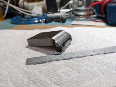
Milled off some of the edge and some of the weld. Think it will be functional to find the corner of the 15 degree tilted block. Haven't tried it yet in the vise, might take some more cutting back of the knife edge so the body of the edge finder doesn't hit.
PXL_20220212_185710704.jpgPXL_20220212_185830075.jpg
Changing topics slightly, my 3/4" end mill with 2.5" LOC came in. Hope my little mill has enough HP to take light cuts with it. Need to square off the end faces of my cast iron block. Really have a devil of a time getting stuff square enough. It's not far off, but, it annoys me to see the light through the edge of the square.

Once the block is squared up, I'll use the tool pictured above to indicate the tilted edge.
 
Hmm. Shouldn't have reviewed videos on squaring a block this morning. Must have jinxed me. Ended up worse (less square) than when I started. :( Won't matter for what I am doing, but it annoys me, a lot. Previously I was 0.5 mm oversize in the 53 and 50 mm dimensions, but relatively square. Now I am almost on size and less square. After indicating and not being able to understand what was going on, decided to stop before mucking it up.

I am finding it difficult to "tap" the block down so that it is level on the parallel. Using a dead blow hammer, but the piece isn't flat on the single parallel by the fixed jaw. It is touching one end but slightly lifted on the other end of the parallel. Using a piece of aluminum wire between the block and the movable jaw. Also, finding the block height on the fixed jaw side is higher than on the movable side. (0.13mm) Maybe tomorrow will make this clearer.

I do know that my spindle light which is attached by magnets, is real efficient at collecting cast iron dust and chips. I suspect some of the chips are raining down on the vise and parallels. Think I will clean it out tomorrow. Probably wrap the spindle light in saran wrap before I put it back on, to make it easier to clean next time!
 
Back
Top