Cletus' PM-935TS-3PH Mill Log

Late last night I started making myself a pair of half-decent T-nuts out of CRS and 1/4" thick washers for holding down my vise to the table. Figured I would do the washers on the lathe, then I remembered I own a CNC Plasma Cutting Table .... the washers were done in 21-secs each (45amps). Now I got to go buy me a 1/2" tap!
:laughing:
T Nuts.jpg
 

Attachments

  • IMG_20211001_153826.jpg
    IMG_20211001_153826.jpg
    3.4 MB · Views: 106
Last edited:
I run my maxi torque rite at 95 PSI. There may be two problems that you may be having. My drawbar was too long for some of my arbors because they were not deep enough, and I almost sheared off the guide pin and ruined an arbor in the process. Tossed the arbor and the guide pin. The other issue with the drawbar is the spindle has to be all the way up and locked on mine other wise it just pushes it down or if and when the threads catch they can get damaged. Third issue the top of drawbar height has to be ~0.050" below the mounting surface. I also get some knocking of the drawbar above 3000 RPM, and have remade the upper spacer/thrust washer that sets the drawbar height.
 
I run my maxi torque rite at 95 PSI. There may be two problems that you may be having. My drawbar was too long for some of my arbors because they were not deep enough, and I almost sheared off the guide pin and ruined an arbor in the process. Tossed the arbor and the guide pin. The other issue with the drawbar is the spindle has to be all the way up and locked on mine other wise it just pushes it down or if and when the threads catch they can get damaged. Third issue the top of drawbar height has to be ~0.050" below the mounting surface. I also get some knocking of the drawbar above 3000 RPM, and have remade the upper spacer/thrust washer that sets the drawbar height.
Thanks Mark, will look into all of the above and correct as necessary.
 
I run my maxi torque rite at 95 PSI. There may be two problems that you may be having. My drawbar was too long for some of my arbors because they were not deep enough, and I almost sheared off the guide pin and ruined an arbor in the process. Tossed the arbor and the guide pin. The other issue with the drawbar is the spindle has to be all the way up and locked on mine other wise it just pushes it down or if and when the threads catch they can get damaged. Third issue the top of drawbar height has to be ~0.050" below the mounting surface. I also get some knocking of the drawbar above 3000 RPM, and have remade the upper spacer/thrust washer that sets the drawbar height.
My guide pin disappeared on its own. Just like my tonsils. LOL. Is it a problem, not having it any more? I have the torque rite power drawbar I got from Matt.
 
My guide pin disappeared on its own. Just like my tonsils. LOL. Is it a problem, not having it any more? I have the torque rite power drawbar I got from Matt.
Good question. My guide pin is in, and all my R8 stuff fits no problem and I had to do no adjustment of the pin depth. I'm still on the fence about leaving it in or taking it out. So far it does not pose a problem for me, so for the time being,I'm leaving well enough alone.
 
I also spoke this morning with Tech Support at All Machine Parts, Manufacturers of the Maxi Torque (really cool people). I wanted to get their thoughts and ascertain where I may have gone wrong, in an effort to mitigate future occurrence of the draw-bar stripped thread issue.
During the conversation and in honestly answering his many questions, I had to admit, maybe it was my fault because of my forgetting sometimes to send and lock the quill fully up before setting or ejecting a collet. This is something I will just have to get used to being constantly aware of and doing as standard operating procedure. He took his time, asked lots of pertinent questions and gave me good solid advice and pointers. Very nice folk to deal with, I am truly impressed.

Some pointers he touched on:
1) Quill fully retracted and locked when inserting or ejecting a collet
2) Item one above, you can get away with it if using smaller tooling, but certainly not anything over 1/2"
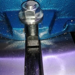
3) Collets and taper need to be clean and dry (acetone or some such), only the draw-bar threads need to have grease.
4) Never leave collets in the quill overnight (expansion and contraction), may cause jams.
 
Last edited:
I just discovered a cool DRO feature that's not in the manual.
One can setup an "alarm" to set the deviation point from zero, when that axis readout changes from black to red. Default value is 0.0008 I've changed it to 0.0002 and can visually get to within +/- two tenths of zero, on any axis, really quickly now. Sure mitigates that last (tenths) digit confusion. Cool little feature! .......did I mention, I really love this display!:cool 2: (Precision Matthews should consider branding and offering these in their product line).

You get to it from the main screen by depressing the point "."
The little alarm window pops up and allows you to enter the value you desire on the keypad and press "ENT" to store it, pressing "ENT" a second time returns you to the main screen.

DRO Alarm Feature.jpg
 
Last edited:
I installed my Align Z axis power feed this afternoon. Wow. Nice addition.
I'm curious about how others have mounted the limit switch and bumpers. My Z axis DRO scales occupy the left side of the machine and the Y axis DRO scale with its dust cover occupy an bit of space on the right side. I'm sure the limits switch has to mount on the right side and I've been considering forgoing the supplied track and mounting the bumpers to the mill with magnets. There's a flat vertical area where they would fit perfectly without having to make a bunch of standoffs.
 
Mine's mounted on the left, but here's a pic anyway, maybe you can do it on the right?
Z Stops.jpg
 
Mine's mounted on the left, but here's a pic anyway, maybe you can do it on the right?
View attachment 381653
Thanks for the clear photo. Most informative. I was eyeballing the corresponding flat area on the right side but the track will not fit on that flat spot because the Y axis DRO scale with its dust cover will not allow it to fit. That was why I was thinking of mounting the bumpers directly to the casting either with magnets or by drilling and tapping. That would allow enough clearance and save me making elaborate standoffs. All I'd have to do is mill off the locating tabs on the underside of the bumpers.
 
Back
Top