- Joined
- Nov 7, 2019
- Messages
- 433
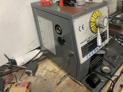
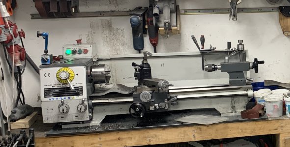
Random thread start but bought this lathe a couple of years ago, maybe 2019 sometime.
It's had a semi-rough life since then, I'm not too kind to my machines.
It's a pretty good machine, especially when you start getting everything tuned in and roughly scrape the surfaces(had a gib not lay flat and the saddle didn't have great contact).
HOWEVER ... A recurring thing for me seems to be breaking gearboxes in machines.
Don't remember exactly what happened but I think I was powerfeeding and really trying to push things.
A second of inattention and I hear the machine bogging down, gearbox is now under so much force that I can't disengage the powerfeed and a second after that I just hear a crack behind the apron handwheel.
A quick teardown reveals this poor guy:
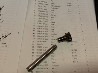
Reseller didn't even answer my emails and only factory I could find wanted ~250 USD for a replacement, for what is basically a 10mm shaft with a gear on it.
I considered making something myself from shafting and premade gears but lowest gear count I could find was 12t and this is a 11t gear.
I don't have the tooling to make gears and didn't feel like doing that investment so I drilled out the center and loctited a long screw in there to hold things together.
This somewhat worked for quite a while but over time you could notice how the apron handwheel "slips" when you're moving the carriage, highly annoying.
Basically the shaft was acting as a clutch because of the broken shaft and loosening loctite.
So a lot like with my mill, I was at the crossroads of either investing a bunch of money to make my own gears or just CNC converting the lathe(which I already wanted to anyway since I more often run into repetitive lathe jobs).
Took some fairly rough measurements and ordered a 1204 and 1605 "ballscrew kit", basically all holders/bearings, the screw and the nuts.
No idea if I could fit it but impulse-decisions is my thing.
This was probably a year or two ago and I haven't had time to deal with it since it's mostly worked "good enough".
Recently however the lathe has been declining in how well it works due to my dodgy repair, so it has become urgent all of a sudden.
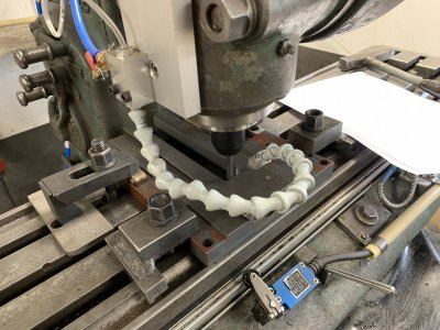
First of I started with moving the lathe, it's been sitting on a wooden bench, only bolted through it's narrow feet's through the plywood sheet underneath, with the studs offset quite a bit from the feet..
The metal tray does some work to spread the load but not much, the lathe was definitely rocking when the chuck was out of balance.
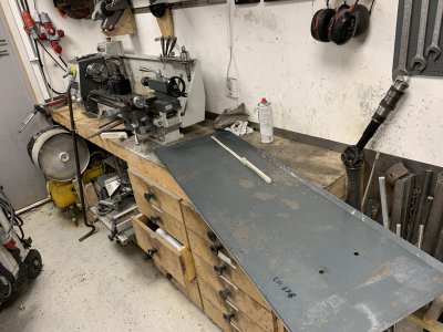
Living on that epic student paycheck I resorted to using scrap steel to improve the situation.
Starting with this massive piece of 12mm steel from some old press.
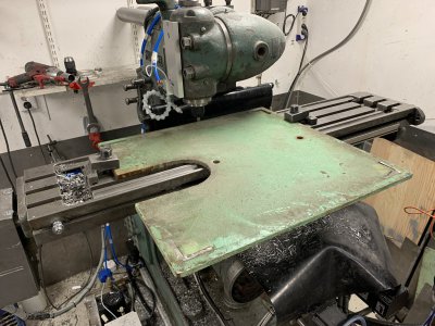
Lots of hours later I have it cut down to size and milled flat, now around 10mm.
I've also managed to tear off my back-cover on the mill because the plate got stuck on it when I didn't notice.
Fix 2 things, break 1 thing. Rinse and repeat.
Luckily it was a prototype cover design so no big deal, if it's that vulnerable I need to redesign it either way.
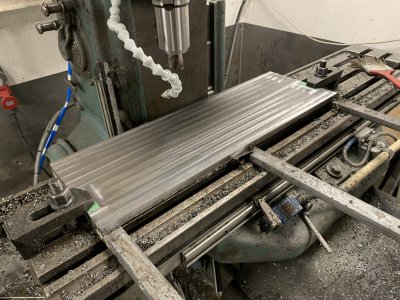
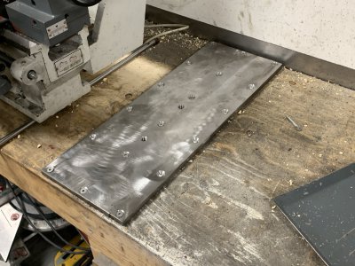
A whole bunch of drilled and threaded holes later.
The idea is to screw this into the studs below and the plywood to spread the load as much as possible.
The lathe with it's tray will then sit on top of this and get bolted down into the threaded holes in the plate.
Made two of these so each "foot" on the lathe gets it's own.
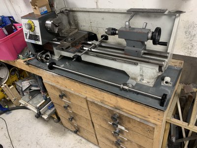
Lathe finally in it's new place, same bench but moved over to the much stronger section.
This let's me run longer stuff through the headstock and combined with the reinforcement plates makes it sit insanely solid now.
I can push it all I got with my 280 pounds with no effect on it, real happy so far.
Next we just got the small and quick project of completely redesigning everything so the CNC-things will fit.
SFU1605 screw along the Z-axis and SFU1204 along the X-axis.
Nema34 steppers for both, 8Nm for the SFU1605 and 4Nm(if I remember correctly) for the SFU1204.
Because the lead is quite high on the screws I will gear them down 2:1, optimally I'd want 3:1 but then the pulleys get so big and hard to place..
Really didn't feel like "trial&erroring" my way through this so spent quite some time in CAD to come up with this.
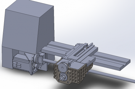
I've tried to keep destructive modifications to the lathe itself to a minimum but in 2 instances I had no choice.
1. The cross slide needed to be milled out to accept the taller/larger ballscrew nut, furthermore two holes were drilled so I can attach the ballnut from above.
2. Because the ballscrew nut is also wider than stock I had to mill out a few millimeters where the nut travels, while doing this I also lengthened the cutout a bit for more travel, guess I got greedy.
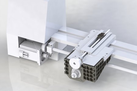
The larger motor(Z) sits on a plate which gets bolted into the original mounting holes for the gearbox which no longer has a use.
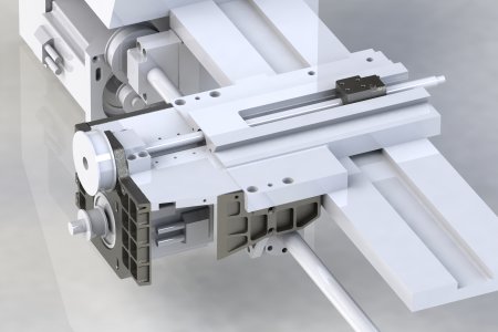
The smaller motor(X) was more difficult to place but gets hidden in behind a bunch of plates that attach to the original holes for the apron.
Easier to see the motor here, just enough clearance to fit it this way, much prefer this look to having it protruding out the front.
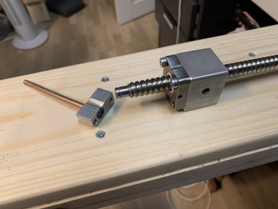
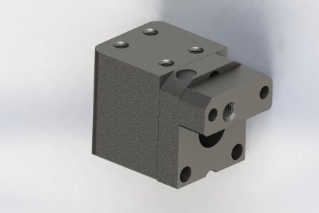
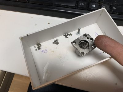
Regarding the nut that I had to mill out both the saddle and cross slide, that's after I've already butchered the nut as much as I dared.
Lower part is cut off, top part is ground down and the grease port is blocked off with a M6 nub that I loctited in place and also peened out the edges on.
A hole was then drilled with a masonry bit to instead get the grease port along the screw instead.
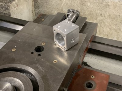
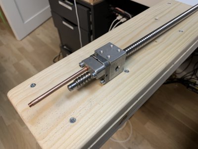
The smaller block(towards the "camera") has a small cutout for an o-ring which HOPEFULLY seals this up once everything is bolted together.
The 4 holes on top go up and bolt through the cross slide, but most likely I will only be using 2 of these.
The worst part of this was having to empty and refill the nut, so I could safely modify it.
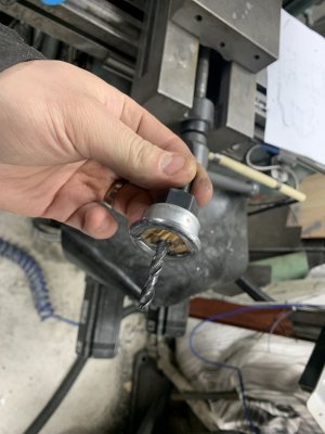
The smaller hole infront of my finger is the new "grease port direction".
Finger, balls and m4 screw for scale so you get an idea of how much fun I had trying to get them back in the nut later.
Then it's just a matter of trying to fit everything onto the lathe and hope I didn't build in too many obstacles.
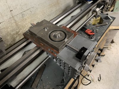
Starting with the X-stuff, it quickly became obvious that widening the slot in the saddle hasn't quite worked out.
I suspect the endmill has dulled because the slot gets narrower the further down you go, despite several spring passes.
I only designed in a clearance of 0.5mm per side so wasn't much room to start with.
Also might as well clarify, everything gray is 3D-printed placeholders before I spent a bunch of hours milling steel.
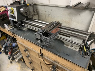
Besides the slot below being a bit too tight, the missing top cover plate and one of the nut screws not threading in, this first testfit was a great success.
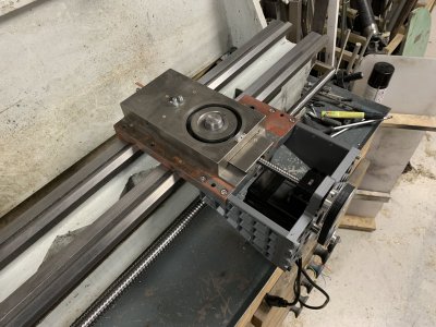
The much simpler part is fitting the Z-screw stuff.
Basically no modifications needed to anything, just need to figure out measurements.
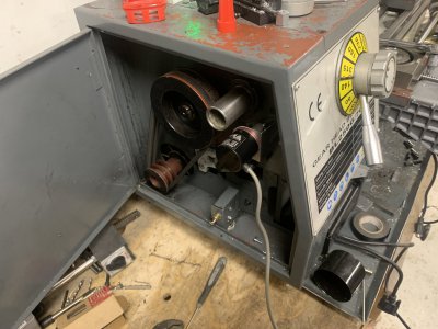
Motor and ballscrew bearing sits on a plate which bolts in where the old gearbox sat.
Could only find one issue here, that the motor can't tension the belt because the slots are not far down enough, easy fix though.
Also need to get proper length screws.
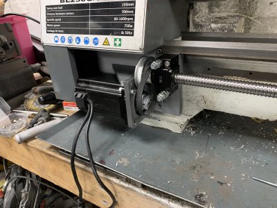
Ballscrew goes out like the usual screw does and has it's nut hidden behind the X-motor.
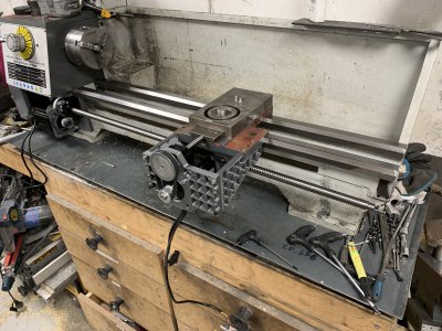
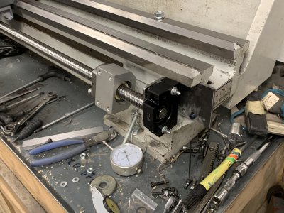
Because it's so long and heavy I want to use it's end-support.
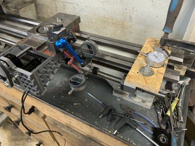
Need to come up with a reliable way of measuring this in perfectly parallel with the ways.
I could probably put a dial indicator on the saddle or something and let it slide along the screw.
Once I have those measurements figured out I can make a plate to extend from the lathe to the bracket.
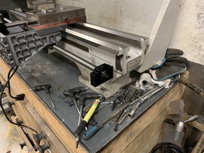
So that's where I'm at currently.
Hopefully it was an inspiring or funny read for someone.
If you see that I've done something stupid somewhere, let me know, I'm just a happy amateur.
It's had a semi-rough life since then, I'm not too kind to my machines.
It's a pretty good machine, especially when you start getting everything tuned in and roughly scrape the surfaces(had a gib not lay flat and the saddle didn't have great contact).

HOWEVER ... A recurring thing for me seems to be breaking gearboxes in machines.

Don't remember exactly what happened but I think I was powerfeeding and really trying to push things.
A second of inattention and I hear the machine bogging down, gearbox is now under so much force that I can't disengage the powerfeed and a second after that I just hear a crack behind the apron handwheel.
A quick teardown reveals this poor guy:

Reseller didn't even answer my emails and only factory I could find wanted ~250 USD for a replacement, for what is basically a 10mm shaft with a gear on it.
I considered making something myself from shafting and premade gears but lowest gear count I could find was 12t and this is a 11t gear.
I don't have the tooling to make gears and didn't feel like doing that investment so I drilled out the center and loctited a long screw in there to hold things together.
This somewhat worked for quite a while but over time you could notice how the apron handwheel "slips" when you're moving the carriage, highly annoying.
Basically the shaft was acting as a clutch because of the broken shaft and loosening loctite.
So a lot like with my mill, I was at the crossroads of either investing a bunch of money to make my own gears or just CNC converting the lathe(which I already wanted to anyway since I more often run into repetitive lathe jobs).
Took some fairly rough measurements and ordered a 1204 and 1605 "ballscrew kit", basically all holders/bearings, the screw and the nuts.
No idea if I could fit it but impulse-decisions is my thing.
This was probably a year or two ago and I haven't had time to deal with it since it's mostly worked "good enough".
Recently however the lathe has been declining in how well it works due to my dodgy repair, so it has become urgent all of a sudden.
First of I started with moving the lathe, it's been sitting on a wooden bench, only bolted through it's narrow feet's through the plywood sheet underneath, with the studs offset quite a bit from the feet..
The metal tray does some work to spread the load but not much, the lathe was definitely rocking when the chuck was out of balance.

Living on that epic student paycheck I resorted to using scrap steel to improve the situation.
Starting with this massive piece of 12mm steel from some old press.

Lots of hours later I have it cut down to size and milled flat, now around 10mm.
I've also managed to tear off my back-cover on the mill because the plate got stuck on it when I didn't notice.
Fix 2 things, break 1 thing. Rinse and repeat.
Luckily it was a prototype cover design so no big deal, if it's that vulnerable I need to redesign it either way.

A whole bunch of drilled and threaded holes later.
The idea is to screw this into the studs below and the plywood to spread the load as much as possible.
The lathe with it's tray will then sit on top of this and get bolted down into the threaded holes in the plate.
Made two of these so each "foot" on the lathe gets it's own.

Lathe finally in it's new place, same bench but moved over to the much stronger section.
This let's me run longer stuff through the headstock and combined with the reinforcement plates makes it sit insanely solid now.
I can push it all I got with my 280 pounds with no effect on it, real happy so far.

Next we just got the small and quick project of completely redesigning everything so the CNC-things will fit.

SFU1605 screw along the Z-axis and SFU1204 along the X-axis.
Nema34 steppers for both, 8Nm for the SFU1605 and 4Nm(if I remember correctly) for the SFU1204.
Because the lead is quite high on the screws I will gear them down 2:1, optimally I'd want 3:1 but then the pulleys get so big and hard to place..

Really didn't feel like "trial&erroring" my way through this so spent quite some time in CAD to come up with this.

I've tried to keep destructive modifications to the lathe itself to a minimum but in 2 instances I had no choice.
1. The cross slide needed to be milled out to accept the taller/larger ballscrew nut, furthermore two holes were drilled so I can attach the ballnut from above.
2. Because the ballscrew nut is also wider than stock I had to mill out a few millimeters where the nut travels, while doing this I also lengthened the cutout a bit for more travel, guess I got greedy.

The larger motor(Z) sits on a plate which gets bolted into the original mounting holes for the gearbox which no longer has a use.
The smaller motor(X) was more difficult to place but gets hidden in behind a bunch of plates that attach to the original holes for the apron.

Easier to see the motor here, just enough clearance to fit it this way, much prefer this look to having it protruding out the front.

Regarding the nut that I had to mill out both the saddle and cross slide, that's after I've already butchered the nut as much as I dared.
Lower part is cut off, top part is ground down and the grease port is blocked off with a M6 nub that I loctited in place and also peened out the edges on.
A hole was then drilled with a masonry bit to instead get the grease port along the screw instead.
The smaller block(towards the "camera") has a small cutout for an o-ring which HOPEFULLY seals this up once everything is bolted together.
The 4 holes on top go up and bolt through the cross slide, but most likely I will only be using 2 of these.

The worst part of this was having to empty and refill the nut, so I could safely modify it.
The smaller hole infront of my finger is the new "grease port direction".
Finger, balls and m4 screw for scale so you get an idea of how much fun I had trying to get them back in the nut later.

Then it's just a matter of trying to fit everything onto the lathe and hope I didn't build in too many obstacles.
Starting with the X-stuff, it quickly became obvious that widening the slot in the saddle hasn't quite worked out.
I suspect the endmill has dulled because the slot gets narrower the further down you go, despite several spring passes.
I only designed in a clearance of 0.5mm per side so wasn't much room to start with.
Also might as well clarify, everything gray is 3D-printed placeholders before I spent a bunch of hours milling steel.

Besides the slot below being a bit too tight, the missing top cover plate and one of the nut screws not threading in, this first testfit was a great success.


The much simpler part is fitting the Z-screw stuff.
Basically no modifications needed to anything, just need to figure out measurements.
Motor and ballscrew bearing sits on a plate which bolts in where the old gearbox sat.
Could only find one issue here, that the motor can't tension the belt because the slots are not far down enough, easy fix though.
Also need to get proper length screws.

Ballscrew goes out like the usual screw does and has it's nut hidden behind the X-motor.

Because it's so long and heavy I want to use it's end-support.
Need to come up with a reliable way of measuring this in perfectly parallel with the ways.
I could probably put a dial indicator on the saddle or something and let it slide along the screw.
Once I have those measurements figured out I can make a plate to extend from the lathe to the bracket.

So that's where I'm at currently.
Hopefully it was an inspiring or funny read for someone.
If you see that I've done something stupid somewhere, let me know, I'm just a happy amateur.


