CNC Journey -- Final Steps?

I bought a conversion kit from Heavy Metal CNC and Bruce recommended using oil on the ball screws. I am using Mobil Vactra #2 on the ways and ball screws. I give all the ways and ball screws a little shot everytime before starting machining.

For reference, I use a Teflon (w/ solvent carrier) dry lube on my 3D printer ball screws, and Nye Lubricant Rheolube on the guide rods. Runs like a top, but its much lower forces so you could probably use just about any lubricant and be OK.
 
Well, I'm stuck on step 9. I've got the Z axis saddle screw out. How does the lead screw drop down? Isn't it supported by the bearings on the plate???
 
Well, I figured it out and I'll post it here in case someone needs this in the future. The Z axis nut needs to be up a couple of inches from the bottom of its travel so the leadscrew with nut can drop down free of the flange at the top. I was assuming the assembly had to go up, but it needs to go down and can't if the nut is near the bottom of its travel since it hangs up on the slot in the column.

Okay, time to install all the ballscrews!!!
 
I have removed ballnuts successfully by turning a straight diameter arbor and unthreading the nut onto the arbor. It will keep the balls in their tracks. But be warned, dropping the balls is really crappy and makes for a not fun afternoon of repacking the nut. It is done from the outside after removing those orange return tracks (you push each ball on one at a time).

Roton ships their ballnuts separately from the screws with a cardboard tube running down the middle of the nut to keep the balls in. Also use a zip tie through the entire assembly to keep the nut retained on the paper tube.
 
Wow! I'm done. :cheerful: All 3 axes have been installed!!! I very happy I decided to get Dave's kit. It saved me countless hours of trial and error and machining.
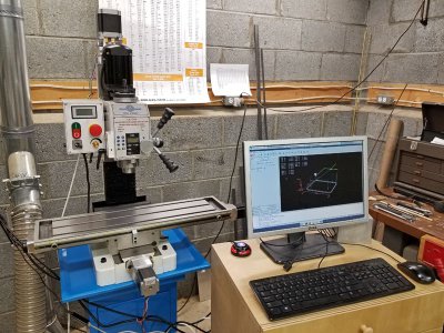
20200405_082040_edit1.jpg

As I suspected, the Z-axis was the hardest. I can say that anyone doing this in the future, be very careful not to drop anything down the column. Don't ask me how I know. :rolleyes: (Ok, I'll talk. I dropped the Aluminum nut. I tried using a wire to snag it and pull it out of the base opening, but it is too high. A magnet wouldn't work either since it is Aluminum. So, I had to unbolt the whole mill from my stand and hoist it up to get it out!)
 
I've been playing with this for a bit now and at the same time getting familiar with LinuxCNC.

I've been trying to measure backlash with my older, inexpensive dial indicator on crappy stand. I think I'm getting between 0.0015" and 0.0020" on X and Y and about 0.0030" on the Z. Does this seems about correct?

Next, I'm trying to determine if the motion is moving the proper amount. I see there is a calibration menu in LinuxCNC. I think I'm out a little bit, but I'm using the same non-ideal setup (dial indicator and stand) plus it has to be aligned exactly parallel with the axis. Is there a better, alternate way to measure this? I have a lot of high-end mics and calipers, but can't figure out how to use them.
 
Do you have a dial test indicator and a couple of 1-2-3 blocks? Even my cheap ones are within a tenth on the length (verified by a micrometer against a standard). If you do, you can align the 1-2-3 block parallel to the axis you want to test. Then you can zero the dial test indicator against the edge of the block (after having taken up all backlash) by sweeping it in the spindle to find the high spot. Then drive it 3” forward. Stick something flat (like a flat top insert or a gage block on the far side of the 1-2-3 block and measure for the high spot the same way you did before. Any deviation from zero will be the error in travel.

Limitations are the accuracy of your 1-2-3 blocks, the resolution/accuracy of your test indicator (a tenths model would be ideal here), and the fact that you are testing over 3”. A better test would be done with a large stack of gage blocks wrung together but a lot of people don’t have these. Repeat this test in various places on the table to make sure you are reading localized lead error in your screw. This is also a very accurate way to measure backlash if you don’t take up your backlash before starting the measurement.
 
Beware that you can make things worse by adjusting the steps/in of your motion controller from a localized measurement. You might make it accurate right there but mess up the rest of the axis’ travel.
 
I have a Starrett Last Word indicator and a couple of sets of 1-2-3 blocks that I know to be accurate within a few tenths. No gage blocks. I don't know what a flat top insert is.

So, I place the block on the table and the indicator in the spindle? Then, move 3" and use another 1-2-3 block against the first?
 
Bingo. Think you got it. You want the tip of the indicator to sweep a small circle (1/8-1/4”) when the spindle is spun. Bring the indicator against the side of the block and spin the spindle to sweep the indicator and find the high spot. Zero there and move 3”. Use something known to be very flat to create a “fence” on the other side of the block and indicate against that.

it helps to have the block lightly clamped to the table for this.
 
Back
Top