CNC Plasma Cutting When You Have No Space

Back in my hot rodding days, I had one neighbor who turned me in to the county zoning Department and even instigated an IRS audit. I never understood how anyone could have such animosity toward a neighbor just because he didn't conform to a particular standard.
 
Last edited:
Gold mine....
 
Awesome build and great source of ideas. I can't access the plans in the download section and I can't seem to get the login to work to become a contributing member. Added complication is 8020 extrusions don't exist "down under" in NZ. There is a local version call Slotpro but it comes in 30mm or 40mm or 80mm square. Not sure if the simple 40mm version ( https://onequip.co.nz/collections/slotpro/4-Series ) will do the business.

At the moment I'm looking at making a variation of this based on materials to hand. I have about 3m of 35mm steel square tube (3mm wall) and similar amounts of 40mm angle (again 3mm thick). A bunch of skate board bearings and associated h/w. I think with that and looking at your original design from "back in the day" I can create a similar design concept without having to resort to the linear guides. I have dual nema34 motors and drivers, a spare mesa card and PS, plus good knowledge of linuxcnc and spare computer and touchscreen. The only thing I think I will need to source will be timing belts (unless I try direct drive) and the rack and pinion (seems to be very cheap)

IF I have some success I can always reclaim the steel back to the stock pile after building a cleaner version with linear guides and perhaps the local SlotPro extrusions.

Thanks for sharing. It's helped a lot generating some really good ideas. Just need to make things work on prototyping budget. :)
 
Continuing on my "on a budget" thinking I was hoping someone (Tmate perhaps) might be able to help with:

[1] On the original build Tmate did I am trying to figure out what bearing arrangement was used to connect to the flat bar. This is the side where the motor is, not the "floating" end. I can see the bearings that will give rigidity to stop the gantry arm from wiggling under motion. I can not see how he is keeping that section of the motion system up. i.e. so it does not slip and slide on top of the flat bar bolted to the 8020 extrusion. Are they flanged bearings? Are there some bearing rollers else where I can't see that are riding directly on the top of the flat bar? Would love to know.

[2] Looking at the cost of linear motion parts where I live I am finding I can source SBR16 rail and associated bearing blocks for half the price of the equivalent square linear guide styles. Would SBR16 with a couple of mounting blocks be a reasonable alternative to the 20 or 25mm linear guides being used/suggested? I'm sure not ideal but for a compromise on a system that is never expected to be 0.02mm accurate does it matter?

Appreciate thoughts and advice.

Cheers - James.

I am no expert, but have been doing a fair amount of research in this thread and equipment and on YouTube.

1) If I understand your question correctly, the square blocks are the bearing that ride on the rail. The only other bearings are the bushings that he used in the drill guide which he as used as a support tube for the gear shaft.

2) I have seen a lot of Plasma tables built with the linear rails you are describing. I have also found very similar blocks to the ones that Tmate has recommended on Amazon for a fraction of the cost of the recommended. My thought is that if you are not going to do production (8/5) every day, then they will probably be fine. From what I have learned, Tmate designed and built a very stout table suitable for industrial use.

I hope I have answered your questions adequately.
 
Papa Charlie - thanks for the response. Appreciate you taking the time.

Re #1 - my question was with reference to his FIRST build. In that one I think he used a linear guide on the gantry cross rail only. It was his bearing setup on the other axis I am trying to unpick. See attached image with the yellow oval showing the specific area of interest. It is these bearings and how this specific linear section is setup from a bearing support point of view I am trying to fathom.

Re #2 - I'm in New Zeland so anything from Amazon larger than a book becomes super expensive due to shipping and now with international shipping capapcity butched by COVID it's even worse. I can ship direct from China okay given their shipping subsidy system. But you take a crap shoot on long items like a rail being striaght on arrival. Much easier to pay a small premium and deal with local suppliers. Anyways, you are correct that this is not production, this is hobby/fun/interest motivated. I will make parts for myself and for friends and others for beer money or just beer. IF it ever gets more involved and I make one-off/small-run parts for money then I will invest in a build more akin to TMate's version with 25mm linear guides all around.

Again, apreciate the time taken to consider the questions and responed.

Cheers - James.
 

Attachments

  • 2x2 casters - focus.png
    2x2 casters - focus.png
    707.6 KB · Views: 29
I will try to shed some additional light on the subject. The machine in the post above only used an origa linear rail and cassette on the Y axis. The X axis used a piece of cold roll steel bar as the rail, and McGill needle bearing cam followers. Two 3/4" cam followers gripped either side of the rail at both ends of the short aluminum extrusion. A single 1" diameter cam follower supported the gantry at both ends of the short extrusion and at the far end of the long extrusion. The cam followers were mounted on 3/16" thick plasma cut brackets.

It would be difficult to use a linear rail on both sides of the X (long) axis partially because of the cost, and partly because of the tolerances in the cassettes/rails. The mere expansion of the table from heat would likely cause binding. With the gantry being merely supported on one end, it is free to move in and out slightly on the cold roll bar as it moves back and forth. The little 2' x 2' table was affordable, as I bought one 48" linear rail and cut it in half. I used an abrasive cut-off saw to do it.

With regard to the cheaper rails and cassettes available on eBay and elsewhere. I have experimented with a variety of these. They typically use ball bearings riding directly on the rail, and fall out without a great deal of provocation. They also get jammed up from the plasma dust rather quickly. The Origa/Parker/Hoerbiger cassettes use captured roller bearings held firmly in place in an aluminum housing with felt wipers at both ends. We have machines out there that have been in daily use for years without a cassette failure.

Please feel free to ask any further questions you might have. I will be happy to help if I can.
 

Attachments

  • cam followers.jpg
    cam followers.jpg
    648.1 KB · Views: 23
Tmate - thank you very much for responding. That pic is perfect and along with your text tells me eaxctly what you had in play. AND I have the parts and tooling in the garage to do make exactly what you have shown either as a 4mm folded structure of 6mm welded fabrication.

Re the cheaper rails etc, yes I have been a bit leery about the grit issues. I think I will pursue a style like your first iteration for X axis and probably a less elegant bearing/v-bearling like setup for the Y (again using what I have quickly to hand). But it should be all pretty mess tolerant while cuttng and a quick rag clean down between sessions will keep the worst of any dust/muck under control.

For the record your version 2 build is super clean and is on the "really want to do it that way down the line" list. :)

A question I thought of: the "T" where these bearing cam follower assemblies are mounted, how much length did you allow for that so as to give enough separation between the follower assemblies to keep the Y axis reasonably ridgid to in relation to X? I've been modeling on circa 250mm. That's about 10".

Cheers - James.
 
Last edited:
A question I thought of: the "T" where these bearing cam follower assemblies are mounted, how much length did you allow for that so as to give enough separation between the follower assemblies to keep the Y axis reasonably ridgid to in relation to X? I've been modeling on circa 250mm. That's about 10".

The longer the better. Note that while the aluminum extrusion is relatively short on the little machine above, the brackets position the cam followers out another couple of inches on each end. The longer your x axis, the greater the separation needed. If both sides are driven, the problem diminishes. On larger machines I have mounted gear racks on the inside of both frame sides and used a double shafted X axis motor and a drive shaft to power the opposite side. The drive shaft was made of 3/4" cold roll round bar, with a spur gear on the end. I had to blow off the gear racks more often, but it worked perfectly. If you have an interest in that approach, I'll dig up a picture or two.
 
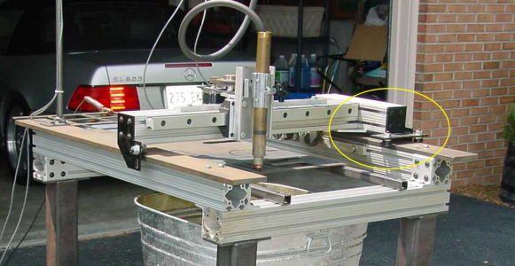
Tmate - I think I'm looking to build the same general sized cut area you are using. You thread title of "CNC Plasma Cutting when you have no space" perfectly describes my situation. I have a garage full of great gear (Good sized, mill and lathe, Surface Grinder, small shaper, small cnc mill, work/wleding table with 1" steel top, welders and blowback start plasma cutter, surface plate and 3 mobile tool chests. So STUFF FOR AFRICA - lol.

Sorry - back on topic, 24" (i.e. 600-610) cut area will be just fine. I am therefore roughly planning on X axis rails of about 1000mm (39.4") and a Y axis rail of about 750-800mm (29.5" to 31.5"). So if you know what your wheel spacing was (roughly) that would be rather useful. 10", 12" or something else?
 
Back
Top