- Joined
- Oct 30, 2019
- Messages
- 197
A coal-fired power plant shut down nearby, and I picked up a few items from there in their auctions last summer. This included a few large new old-stock pressure tanks for water systems ($25 for two tanks that are $800/ea new), a flammables storage cabinet, and a 1998 Ford Ranger.
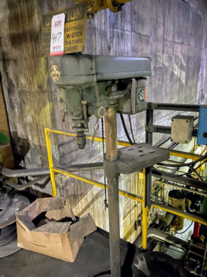
Amongst this was a Walker-Turner drill press for $125. This may have been a good deal, another one in the same auction on the same day went for twice that -- but that one was in the indoors machine shop. This one was out in the plant, covered in coal dust and showing decades of rough use.
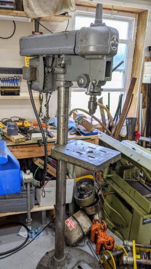
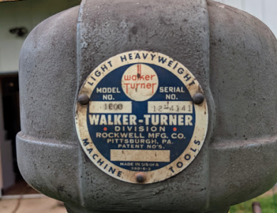
Here was one of the pictures available during bidding:
Upon getting it home I gave it a quick triage
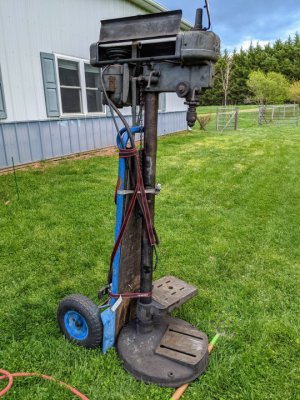
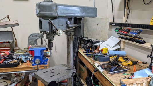
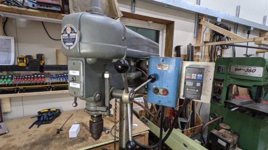
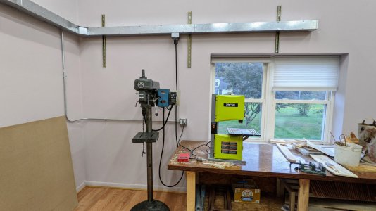
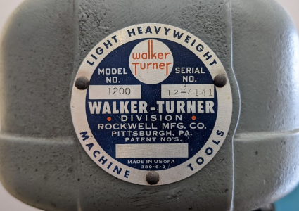
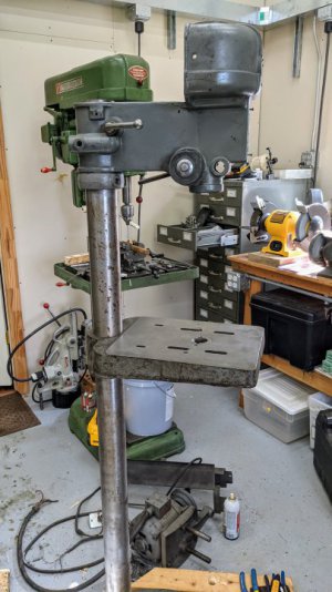
Here it is in the shop near my Powermatic 1200. The Powermatic 1200 is much heavier, more powerful, larger in almost every way. However the W-T is almost the same height and would cover probably 80% of the same use cases. This aligns with the titling of "Light Heavyweight" on the badge
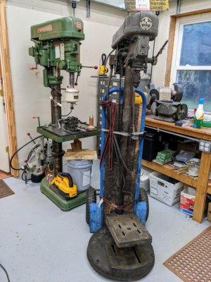
Triage continuing...
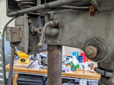
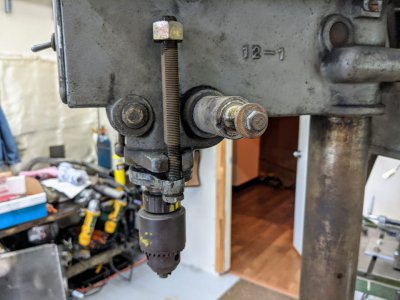
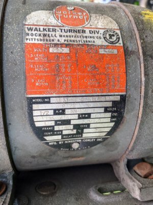
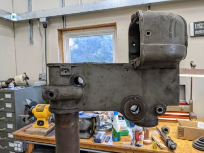
Begin the disassembly, every part of this would need a cleaning and fresh lubrication. Stripped every part off the upper casting
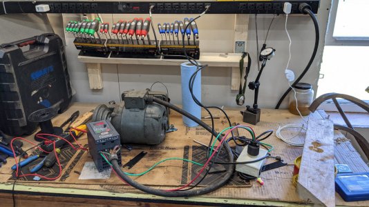
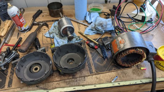
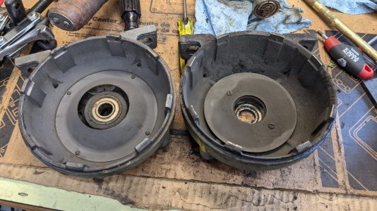
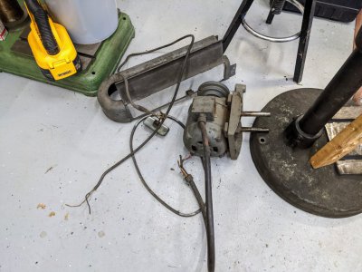
As well as the motor, covers, wiring
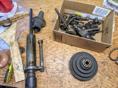
Everything that fits is destined for the ultrasonic cleaner (purple Simple Green diluted ~ 4:1)
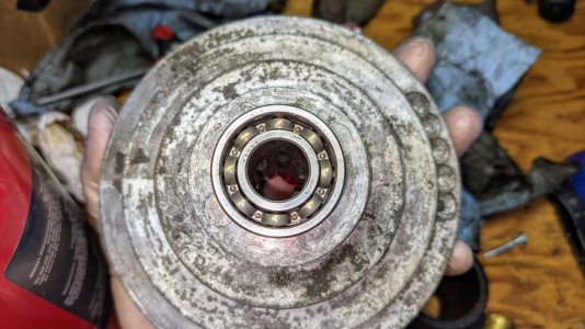
I wouldn't be surprised if the grease in the cone pulley bearings is original. Note how black the pulley is, it is absolutely caked in sticky dust.
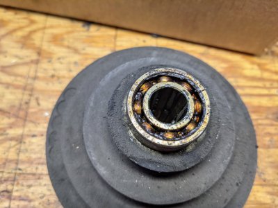
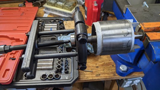
I put everything in the ultrasonic cleaner, including the cone pulley to dissolve the grease out. These bearings in the W-T cone pulleys have a reputation for being extremely difficult to remove without damaging the pulley, which I did not want to risk. The bearing otherwise seemed healthy.
While all the small parts were taking a bath, I wanted to disassemble and inspect the quill further. I don't know how someone did this, unless they dropped the quill when it was outside the machine; but the top of the quill was peaned over pretty badly. This prevented removal of the spindle and bearings
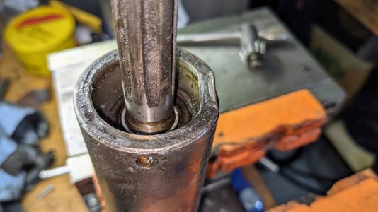
I took a die grinder with a carbide burr to the damage, which then allowed the bearings and spindle to be removed.
With the spindle removed, I could chuck it up in the lathe and evaluate the runout
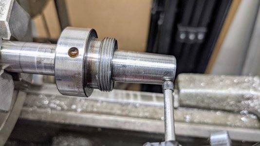
I roughly located where the bend was, and set about trying to correct this. At first I started in the vise, with some pieces of aluminum and brass to let me concentrate the bending forces while avoiding damaging the surface
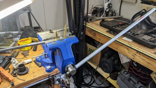
I removed most of the runout this way, but could not overcome the elasticity of the remaining bend -- even with the cheater pipe shown. At this point I walked over to a neighbor's house and used his shop press to accomplish the same task. At first I over-corrected slightly, but then through numerous iterations I did get the runout sufficiently improved for the future life of this aging machine.
Each iteration consisted of measuring+marking the runout in the lathe at home; then walking next door; setting up in the press; making the [estimated] adjustment; then coming back home and re-marking to repeat the process.
Ultimately I got the runout down to approximately .002", and couldn't really do better than this without more time and easier access to a press (shorter distance and time between measuring/marking+adjusting).
I did also buy a MT1 replacement quill assembly on ebay. However, I did want to try to repair this spindle since it had the JT33 with the retaining collar. This has specific value with where I intended to use this drill press (explained further down)
At this point the parts in the ultrasonic were all clean
Pulley ready for new grease, and the casting is a completely different color and texture than before.
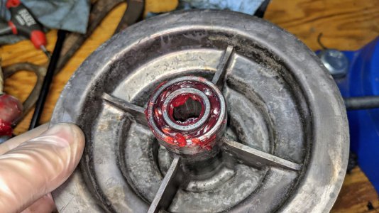
I gave all the other parts a quick shot of light oil or wax (depending on where they were being reinstalled), to prevent rust while they sat waiting for reassembly.
Now turning to the major structural components...
These were scrubbed down with Simple Green and a drill brush inside, then eventually taken outside where I hit them with some heavier degreaser, more drill brush, and the pressure washer. Not perfect, but this is a repair rather than a restoration.
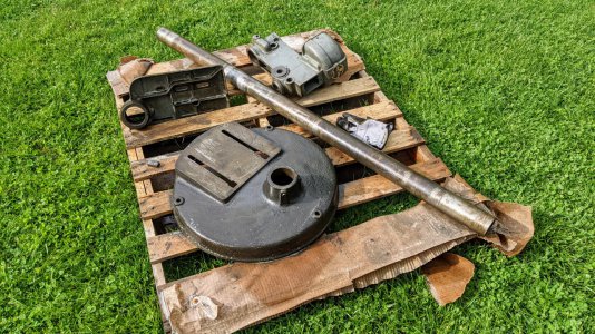
Dried off, and I hit everything with some paste wax to resist rust.
I will write up the rest of the repair and assembly in a reply to this post due to the attachment limit
Amongst this was a Walker-Turner drill press for $125. This may have been a good deal, another one in the same auction on the same day went for twice that -- but that one was in the indoors machine shop. This one was out in the plant, covered in coal dust and showing decades of rough use.
Here was one of the pictures available during bidding:

Upon getting it home I gave it a quick triage

Here it is in the shop near my Powermatic 1200. The Powermatic 1200 is much heavier, more powerful, larger in almost every way. However the W-T is almost the same height and would cover probably 80% of the same use cases. This aligns with the titling of "Light Heavyweight" on the badge

Triage continuing...


- 1/2 hp 3ph motor
- One of the downfeed handles is missing, and the other two are missing their ball/knob ends
- Does not have the optional jackshaft in the middle for slower range of speeds
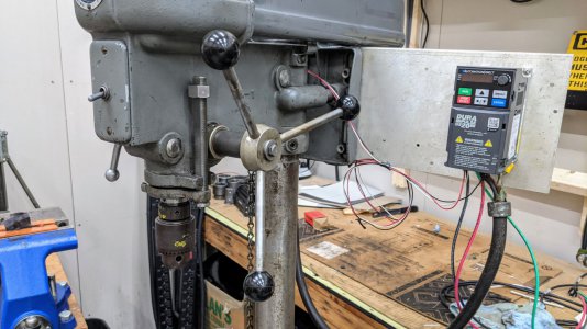
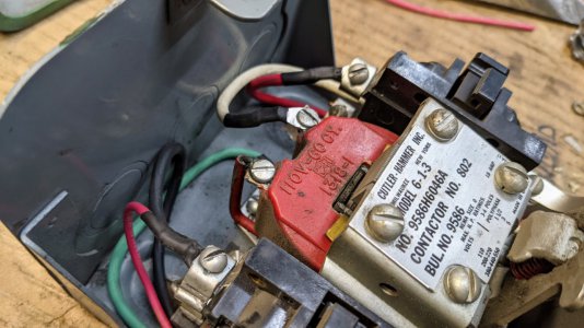
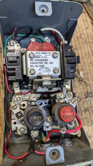
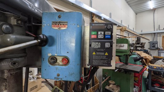
- It came with a motor starter and transformer that were mounted to the wall. The auctioneer was patient enough to let us remove those and take them. The transformer provided 110v from the 208v 3 phase available (no neutral was run to the area of the machine). This 110v was in turn used to allow the switch to provide an external pilot to the motor starter.
- The thing is filthy; coal or coal-adjacent dust everywhere
- Nothing moves/slides nicely
- This thing must have been used to solve all manner of plant issues when people weren't being gentle or overly careful with what they were doing , it just felt like it had a rough (but not abusive) 5+ decades in service
- Measurable runout in the spindle, approximately 0.010" with the quill retracted and .020" with it extended
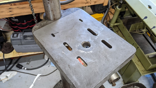
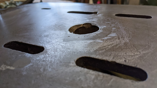
- Castings all appeared in good shape, except for a few holes drilled in the table
Begin the disassembly, every part of this would need a cleaning and fresh lubrication. Stripped every part off the upper casting

As well as the motor, covers, wiring

Everything that fits is destined for the ultrasonic cleaner (purple Simple Green diluted ~ 4:1)

I wouldn't be surprised if the grease in the cone pulley bearings is original. Note how black the pulley is, it is absolutely caked in sticky dust.

I put everything in the ultrasonic cleaner, including the cone pulley to dissolve the grease out. These bearings in the W-T cone pulleys have a reputation for being extremely difficult to remove without damaging the pulley, which I did not want to risk. The bearing otherwise seemed healthy.
While all the small parts were taking a bath, I wanted to disassemble and inspect the quill further. I don't know how someone did this, unless they dropped the quill when it was outside the machine; but the top of the quill was peaned over pretty badly. This prevented removal of the spindle and bearings

I took a die grinder with a carbide burr to the damage, which then allowed the bearings and spindle to be removed.
With the spindle removed, I could chuck it up in the lathe and evaluate the runout

I roughly located where the bend was, and set about trying to correct this. At first I started in the vise, with some pieces of aluminum and brass to let me concentrate the bending forces while avoiding damaging the surface

I removed most of the runout this way, but could not overcome the elasticity of the remaining bend -- even with the cheater pipe shown. At this point I walked over to a neighbor's house and used his shop press to accomplish the same task. At first I over-corrected slightly, but then through numerous iterations I did get the runout sufficiently improved for the future life of this aging machine.
Each iteration consisted of measuring+marking the runout in the lathe at home; then walking next door; setting up in the press; making the [estimated] adjustment; then coming back home and re-marking to repeat the process.
Ultimately I got the runout down to approximately .002", and couldn't really do better than this without more time and easier access to a press (shorter distance and time between measuring/marking+adjusting).
I did also buy a MT1 replacement quill assembly on ebay. However, I did want to try to repair this spindle since it had the JT33 with the retaining collar. This has specific value with where I intended to use this drill press (explained further down)
At this point the parts in the ultrasonic were all clean
Pulley ready for new grease, and the casting is a completely different color and texture than before.


I gave all the other parts a quick shot of light oil or wax (depending on where they were being reinstalled), to prevent rust while they sat waiting for reassembly.
Now turning to the major structural components...
These were scrubbed down with Simple Green and a drill brush inside, then eventually taken outside where I hit them with some heavier degreaser, more drill brush, and the pressure washer. Not perfect, but this is a repair rather than a restoration.

Dried off, and I hit everything with some paste wax to resist rust.

I will write up the rest of the repair and assembly in a reply to this post due to the attachment limit
Last edited:


