Cord Clamps for my Huanyang VFD.

7milesup

H-M Supporter - Gold Member
H-M Supporter Gold Member
Joined
Jan 7, 2016
Messages
3,259
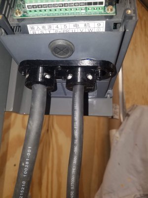
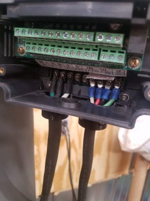
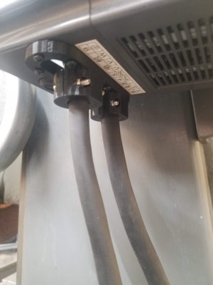
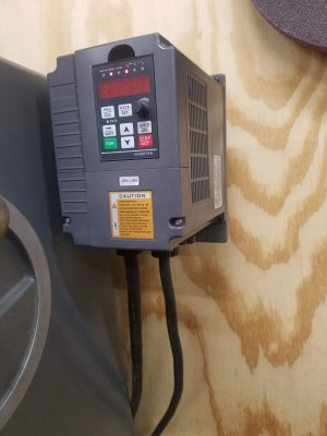
After purchasing a Huanyang VFD to convert my single phase 220 to 3 phase 220 I discovered that the cable management sucks on this VFD. Not only are the terminals quite small considering the size of wire I wanted to use, but the wire cord was going to hang from those terminals. I tried using a small hole saw to make provisions for the typical metal wire clamp, but the end result was not good. Not enough room for the nut and the protruding wire clamp into the VFD. So, off to the house to fire up Solidworks on the old confuser and then 3D print my result. I think it turned out pretty darn good. I left some of the area around the cord clamps open, just because. I could easily print another one and close it up.

Here is a linky to the thingy on Thingverse. https://www.thingiverse.com/thing:4542400
 

Attachments

  • 20200713_195025.jpg
    20200713_195025.jpg
    713.2 KB · Views: 48
  • 20200713_195036.jpg
    20200713_195036.jpg
    727.5 KB · Views: 49
  • 20200713_195046.jpg
    20200713_195046.jpg
    555 KB · Views: 51
  • 20200713_195542.jpg
    20200713_195542.jpg
    699.4 KB · Views: 47
  • VFD cord holder.SLDPRT
    411.4 KB · Views: 4
Last edited:
Aren't you supposed to use only two of the RST terminals for single phase? Looks like you have the input ground hooked to the R terminal, I believe that is wrong.

Hmmmm. Well, I have had it running for a while like this, but now after doing a little poking around you may be correct. The sheet that came with the VFD shows 220 input to RST with no order. I will look into this further.
 
My books say to use any two of the RST, for single phase input, and all three for three phase input. I guess the ground, is interpreted as no power input on that line, but also fear it could be leaking power back to the ground.
 
My books say to use any two of the RST, for single phase input, and all three for three phase input. I guess the ground, is interpreted as no power input on that line, but also fear it could be leaking power back to the ground.
Yep, I see your point. Now I am questioning where the ground would go to. #9 is a ground but that is for the output side. Could the ground on the input be tied to ground on the output?
Good thing this is my thread because we are heading off the tracks....
 
Thats almost the way I did mine. The grounds are grounded to the metal cabinet the VFD is in, and then one wire goes to the VFD ground.
 
Thats almost the way I did mine. The grounds are grounded to the metal cabinet the VFD is in, and then one wire goes to the VFD ground.
Ok. I will redo that then. Thank you for pointing out my error.
So, what about my 3D printed thingy huh? I will bet you want one... LOL. j/k

I just acquired a metal box so this may end up in that enclosure. I would still utilize the 3D printed strain relief though.
 
Just be sure you do not do anything that will cause heat buildup. Right now, I keep the cabinet open when using the VFD. I plan to add a fan and filter, along with a computer fan controller that turns up the fan when it gets warmer.
 
Looks good, That unit is a dead ringer for my Teco-Westinghouse L510
 
That unit is a dead ringer for my Teco-Westinghouse L510
Not really, totally different other than they both have a plastic case. One of the significant issues I found with the HY VFD's is that the terminals arrangment and their size does not support the current ratings/wire gauge. The few installs I did with them I had to cut down the terminals so they would fit. The ground should be to the metal case, but the ground terminal is on the other output side. You can also use a star or bus ground in an enclosure/back plate and tie all the grounds to a single point. Surprised nothing went south with the ground connect to the R terminal, but then it just connects to an input diode. A common confusion I have seen in many VFDs is their designation for the other pole of 240VAC is N, and people sometimes connect a neutral to the terminal. The VFD doesn't run well off of 120VAC input.

You make a good point about using some form of strain relief so the cables are just not hanging, also convention is to use two methods to secure the power wires so crimp with fusing shrink tubing and some form of strain relief. Also do not tie the control wires to the VFD motor cable due to electrical interference.
 
Back
Top