Couple of "quick" motor wiring questions

ScrapMetal

Active User
Registered
Joined
Apr 6, 2011
Messages
2,082
I'm coming getting very close to the point where I'm ready to plug my new (to me) mill in but I need to be a little more clear on a couple of things before I go plugging it in and throwing the switch.

To give a bit of background, I just pulled in the 3-phase from my nearby office to my "shop". The power is 3-phase, 4 wire, 208v. Now, that means that (in my case) I have 4 wires coming in to my box and they are marked as black, red, blue, and white. The "white" wire is the neutral/ground and all the white and green wires in the box are connected together. Now, I just changed out the plug on the mill to match my receptacle BUT the mill's power cord also has 4 wires and they are green, white, black, and red. The green in the power cord is grounded to the body of the machine.

Does this mean I should match my white wire (from the box) to the green wire in the power cord and also connect the blue wire (from the box) to the white power cord wire? (Not that there are many options I just want to make absolutely sure of things before I accidentally let the magic smoke escape.)

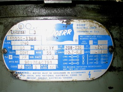
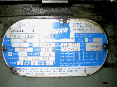
My next question is about the re-wiring of the motors for 208/220v. I understand the wiring diagrams on the motor plates:
WIhorizontal.JPG

No problems there except for the fact that I have "reverse" switches on both motors, a Cutler-Hammer "9441" on the horizontal and an Allen-Bradley on the vertical. Do I change the wiring between the switches and the motors (my guess) or before the switches and will I also need to figure out how to re-wire the switches in either case?

Thanks guys,

-Ron
WIhorizontal.JPG
 
White isn't really for ground, normally. When using a wire for a non-standard location, I wrap a little tape (green in this case) to indicate the intended use. So then you would effectively have a ground (white w/ grn tape) and three hots. That should make it more or less standard to anyone who comes after you also.

On the power cord, you have a real ground (green) to attach to the faux green (taped) ground, and then the three hots, whatever color they are, even if one is white. Even then, I would tape the power cord white another color to make sure no one assumes it to be Neutral.

The wiring should be correct and documented before getting to the switches, and all the reversing done by the switches.

Thanks Tony, good idea with marking the wiring with green tape. Now I gotta get some green tape! :p (I thought I was "living large" with my collection of black, white, red, and blue.) I'll have to keep the color coding that I am using now but I will add the extra tape to either confuse 'em more or possibly help later on. My reason behind this is that even though the "shop" is separate from the office building, it is still fed from there and I would like to keep the wiring/color conventions consistent throughout the circuit. I may have to write myself a note and tuck it into the boxes so I don't forget what the heck I did. :huh:

The more I think about my second question on the motors' wiring, the less sense I think it made. (Another long day at the office, running conduit in the shop, pulling wires, etc.)

I'm going to try that question again but only after I have some time to spend staring at the innards of the switch boxes to see if things will coalesce into a clear understanding of what goes where. A guy can dream, can't he? :p :biggrin:

My son and I are going to make a short trip tomorrow to pick up fireworks so I'm not sure if I'll have time to be in the shop. Next time I'm in I'll try and take a couple pics to spice up this thread a bit. ;)

Thanks,

-Ron
 
Ron,

Journeyman electrician talking here now. (Even if from a different country.) Shut down your feed to the shop panel the next time you get out there and disconnect all connections between ground and neutral except the one at the main panel in the office. More isn't better. Since the new shop panel may be out-of-the-box new, there will likely be a brass screw or strap from the neutral bus to the box. Remove that as well.

The only place the neutral should (and must) be connected to ground is where the power comes into the system in the main disconnect, which, in smaller systems, may be the main breaker in the first panel. After that point, any connection between ground and neutral creates a loop that sets up weird ground currents that can cause problems, up to and including burning off connectors on armoured cable.

The fourth wire in the cable is only white because that's the way that type of cable is made by all manufacturers. If you were using TEK cable, that one would be blue. We normally mark it with white tape when used for the neutral, leave it blue in three-phase systems. Tony's suggestion of marking the white wire another colour (normally blue) is a good one. White is never ground in North America. Ground (bonding) conductors are never allowed to be used as neutrals.

The neutral is a grounded hot connection. The ground is intended to pin the voltage to 0 volts, relative to ground. (Makes sense.) Floating neutrals can allow unexpected voltages somewhere in the system. Potentially (pun intended) not fun. The neutral is intended to carry the unbalanced load. If all three legs have exactly the same current flowing, there will be no current on the neutral. Thats why one neutral can service three hots. It will never carry more current than any one hot.

BTW, is there a ground stake or plate connected to your shop panel? (Bare ground coming into the panel and connected to the box or the neutral with a connection from neutral to ground.) There shouldn't be, for the same reasons stated above.
 
NEC Article 250 addresses grounding and the bonding of said ground to other conductors, and as a rule disallows the neutral to be connected (bonded) to ground at any point outside the service entrance enclosure. If you have a resource that differs, please provide reference.
 
Thanks for all the discussion guys - gave me quite a bit to consider and do more research on. (Yes, reading through the NEC rules is rather mind numbing. :faint:) On this system, the neutral leg is tied to ground in the panel(s) as it should be. There is also a ground rod through the floor with a bare connector up to the panel that remain intact (I always thought those were in case of lightning strikes. :thinking:).

Now, to quote the once eminent Dr. Frankenstein, "It's alive!" :thumbzup: None of the magic smoke leaked out even! The only thing left to do is to get some green tape to mark a wire as "ground" instead of neutral (even though they are tied together) it was still a good idea for future reference/access. (Thanks Tony!)

I found the re-wiring of the motors was as simple as could be once I got going on it. All the connectors and the switch innards make it appear to be more complex but in reality they are a "non-issue". Just follow the wiring diagrams on the motors and "viola!" what was once 460v is now 208v/230v.

Ran both motors both in forward and reverse just to make sure nothing was buggered up and all tested out positively. Both motors run smoothly and I believe what little noise there is comes from the belts/gearing. I didn't run anything for an extended amount of time as I have not yet procured the proper lubricants.

Thanks guys,

-Ron
 
Sounds good Ron. We love a success story!
 
Back
Top