- Joined
- Oct 31, 2016
- Messages
- 2,643
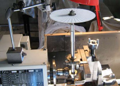
John you are thinking of my sketch as if it were a dividing plate. There are no holes to count. no pins to engage or sector arms. You do need a pointer. Not having a dividing head and never having used one I don't know if they have a pointer. To be honest after reading how to use a dividing plate it sounded like a recipe for disaster.
All you do is rotate the sketch from one line to the next as you cut each tooth on the gear. If you should happen to skip a line or two you can always go back and cut the missed line The amount of possible error depends on the diameter of the circle. larger is better, and the thickness of the lines, thinner is better. I did the math based upon an 8" diameter circle and the thinnest line my printer would print. The maximum possible error was a couple of thousandths on any given tooth.
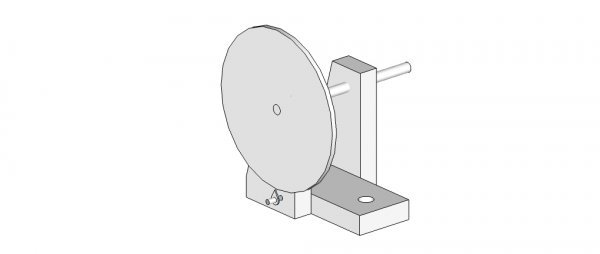
I did not come up with this on my own. I was researching how to make gears because I need a couple for future projects to be able to cut metric threads. I found an article or it may have been a you tube video where a guy explained how he made gears with the milling attachment on his lathe. If I can find it I will post a link. One of my future projects is to make a simple fixture to cut gears. Here is a rough sketch of my fixture to show the concept.

The sketch is very rough and doesn't show details like how the gear blank would be attached to the shaft or how I would lock the shaft in place.
All you do is rotate the sketch from one line to the next as you cut each tooth on the gear. If you should happen to skip a line or two you can always go back and cut the missed line The amount of possible error depends on the diameter of the circle. larger is better, and the thickness of the lines, thinner is better. I did the math based upon an 8" diameter circle and the thinnest line my printer would print. The maximum possible error was a couple of thousandths on any given tooth.
I did not come up with this on my own. I was researching how to make gears because I need a couple for future projects to be able to cut metric threads. I found an article or it may have been a you tube video where a guy explained how he made gears with the milling attachment on his lathe. If I can find it I will post a link. One of my future projects is to make a simple fixture to cut gears. Here is a rough sketch of my fixture to show the concept.

The sketch is very rough and doesn't show details like how the gear blank would be attached to the shaft or how I would lock the shaft in place.


