- Joined
- Feb 7, 2013
- Messages
- 2,485
For some odd reason, after after owning my Springfield lathe for 20 years, I took issue with the fact that someone had
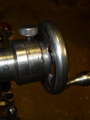
welded the advance indicator dial to the crank and had thrown away the knurled bolt. It's nice to have two lathes
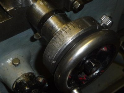
as I took the crank handle off the Springfield and put in the Monarch and machined the welds to separate the crank
wheel from the indicator dial. The crank looked rough so I did some die grinding to make it halfway presentable.
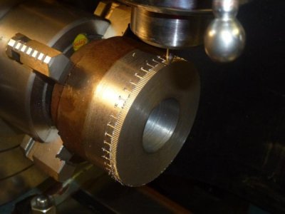
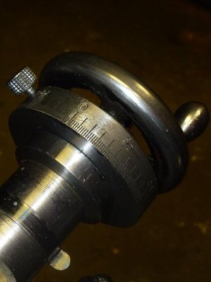
Then I made a knurled bolt 1/4 x 20 to fit on the dial. So far so good. Now the problem is that the dial ring binds in places and
is a constance source of aggravation. It seems the dial ring is not of uniform thickness something not just right. The
parts had been welded on so that is no big surprise. Also, the dial could be easier to read so I am considering
making another one in grander scale probably. I figured that if I make this post and announce that I am going to
rework the dial, I will get right on it and make another post of a new dial. Hopefully so.
Here's a photo of how it looks after I worked on it this morning:


 (I'm trying to transform a sow's ear


