Cunliffe Mill Electrical Problems

Ok, thanks Mike... :)

I'll get to that maybe tomorrow afternoon.

Brian :)
 
I'm back again... :)

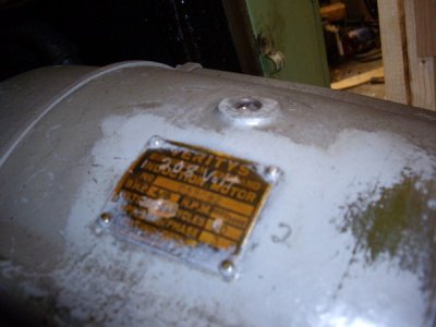
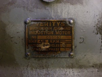
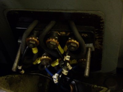
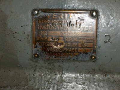
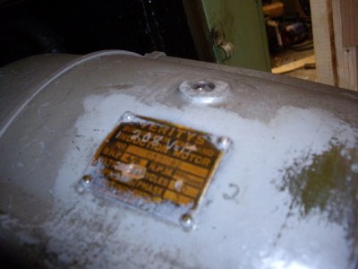
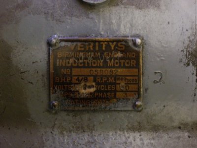
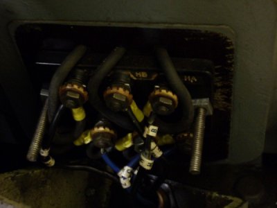
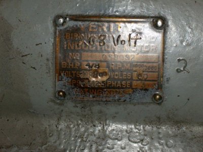
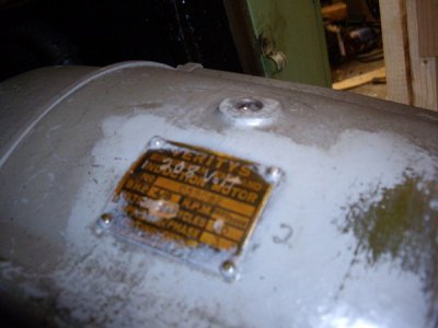
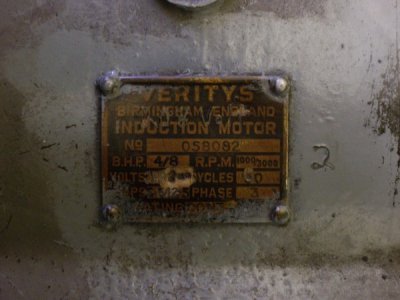
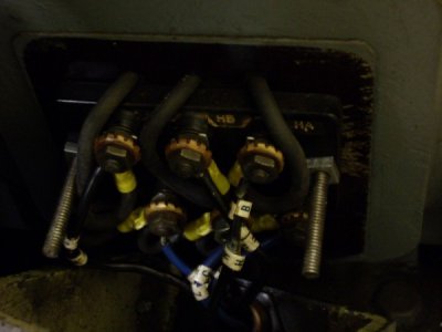
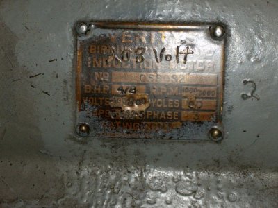
I finally had a chance to slide the main mill motor out of the base to get at the nameplate as well as the wiring. The pics aren't great, but might be clear enough to glean some information.

IMGP1045800x600_zpsd40c6bd4.jpg

IMGP1046800x600_zps97093b46.jpg

IMGP1047800x600_zps8fcdcf49.jpg

IMGP1049800x600_zpsd767b8a0.jpg

It appears that the motor has been rewound to 208v/ 60 cycles. There are 6 wires coming out of the motor and the connections look straightforward. Maybe you experts can tell if it is wired properly.

I checked the amperages of the RPC and this is what I read...

L1 Inrush... 140a
At Idle... 8a

L2 Inrush... 130a
At Idle... 8a

I then checked the amperages of the RPC with the mill motor running...

L1 Inrush... 65a
Mill running without clutch engaged... 17a
Inrush with clutch engaged... 22a
Mill running... 17a

L2 was within 1 amp of L1.

I must go snowblow my driveway and will check back in a little while...

Brian :)

IMGP1045800x600_zpsd40c6bd4.jpg

IMGP1046800x600_zps97093b46.jpg

IMGP1047800x600_zps8fcdcf49.jpg

IMGP1049800x600_zpsd767b8a0.jpg

IMGP1045800x600_zpsd40c6bd4.jpg

IMGP1046800x600_zps97093b46.jpg

IMGP1047800x600_zps8fcdcf49.jpg

IMGP1049800x600_zpsd767b8a0.jpg
 
It appears that the motor has been rewound to 208v/ 60 cycles. There are 6 wires coming out of the motor and the connections look straightforward. Maybe you experts can tell if it is wired properly.

Do these six wires go from the motor to the starter panel and if so, do three connect to one of the contactors and the other three connect to the other contactor?
 
Hello den-den,

At this point, I don't have the answer to that. Inside the motor cavity are numerous armoured cables and "T" junctions to supply the other two motors as well as a light. There isn't much room, but I will try and see where the wires go to.

The contactor on the left ( the one that doesn't engage ) has three white wires coming to the bottom of the contactor and there aren't any white wires that are wired into any of the motor leads. In addition, these white wires are of braided wire, while all of the original wiring inside the panel is solid copper, so I assume that this may have been done when the two motors were rewound.

I removed the flash guards on the contactors and found some wear and slight pitting on the contacts, but nothing jumped out at me. I removed each hold-down spring and cleaned up the copper contact areas while I was at it.

Canadian commercial 3-phase voltages are typically 208v from what I was told. Both of the motors on the mill have been rewound to 208v. Also, the idler motor is a Leeson motor with a 208v rating. My RPC panel was bought out of the U.S.A. and is producing approximately 240v. Is this a concern in the present situation ?

Brian

Hi Brian,
i'm thinking the contactor on the left is the pump motor contactor because the current limit on the 4amp Overload relay is for a small motor- it's probably not going to pull in unless you actuate the pump switch.

slight pitting is completely normal for electrical contacts- no worries there.

US 3 phase Wye Transformed power is also stepped down to 208vac, most of my grocery stores are supplied 208 vac.
using 240 from the RPC most likely is not going to hurt you in this case. electrical tolerance is usually 10%
240-24=216 or (8 volts beyond tolerance for a milling machine no big deal) i routinely run equipment rated 208 on my 240 supplied RPC.
you'll have the added bonus of total circuit amp reduction, a motor at 240vac will pull less amps than the same motor on 208vac due to the increased voltage
Ohms Law states that amperage is inversely proportional to voltage-
When volts are higher, the amperage required to do the same work is lower and vise verse, when the resistance is constant.

the blue wires appear to have been added when the 208v rewind was done.

the last picture is really dark for the motor connections , can you take a picture with a flash or a flashlight so i can better see how it's wired?
Cheers,
mike
 
Last edited:
as i'm racking my brain on this-
i started another line of questioning in my head,i'm writing out loud so bear with me.

did the spindle turn in the correct direction when you originally turned on the mill in the high speed position
(when it sounded bad and attempted to run)?


let me know if i'm starting to confuse you, if so we'll take one thing at a time.

were going to compare some things in a minute...
 
Last edited:
Hello Mike,

Well, that is all good news. I don't have the base filled with coolant, but I might try to start the pump for just a few seconds and see if the left contactor pulls in.

What do you think the next step might be ?

Brian :)
 
Oh, there you are... :)

No confusion here, Mike... :) at least not at the moment... ;)

Yes, the spindle turned in the same direction as when the low speed setting was engaged. On this particular mill, spindle direction can be reversed mechanically through a gear lever.

When the high speed setting was turned on, the motor seemed to take an inordinate amount of time to come up to speed, compared to the almost instantaneous low speed setting.

I did manage to get the high speed setting to run up just the one time and also engaged the clutch and had the spindle turning. It only shut down because I shut it down to change the speed selector and try it in the other settings.

Brian
 
Mike, here's something that I looked at this evening...

C and A in the RPC panel are the incoming single phase lines and B is the "wild leg". Inside the idler motor, I had the "wild leg" hooked up to L2, so to speak. I have since changed that to L3. Then, where the 3-phase power comes out of the RPC to a female plug, I made sure that the "wild leg" goes to L3 in the mill panel terminal.

Before I did this, the "wild leg" went to L2 in the idler motor. Would this have had any affect on the issue ?

Brian
 
Hello Mike,

Well, that is all good news. I don't have the base filled with coolant, but I might try to start the pump for just a few seconds and see if the left contactor pulls in.

What do you think the next step might be ?

Brian :)


Hey Brian,
you could try it and see, it won't hurt the pump for a quick check.
i'm not telling you to do this-
but, in the field if i want to know if a machines' problem is control oriented or motor oriented i take one simple step after exposing the contactor panel,
i take an insulated screwdriver and physically actuate the contactor with the screwdriver.
if the motor runs, i (or you) then can deduce the control circuit is at fault.
in machinery, 3 phase motor circuits are(generally) supplied with main voltage and broken by means of contactors that are controlled by the control circuit. sometimes the controll circuit is the same voltage as main voltage(as in your case) , most times control voltage is lower than main voltage in machines for US Industry .
 
Last edited:
Back
Top